
US 10930
UNITED STATES PATENT OFFICE.
JEREMIAH PECK, OF NEW HAVEN, CONNECTICUT, ASSIGNOR TO J. PECK AND CHAS. F. GRILLY.
IMPROVEMENT IN FIRE-ARMS.
Specification forming part of Letters Patent No. 10,930, dated May 16, 1854.
To all whom it may concern:
Be it known that I, Jeremiah Peck, of the city and county of New Haven, in the State of Connecticut, have invented a new and useful Improvement in Revolving-Breech Fire-Arms; and I do hereby declare that the following is a full, clear, and exact description of the construction, character, and operation of the same, reference being had to the accompanying drawings, which make a part of this specification, in which—
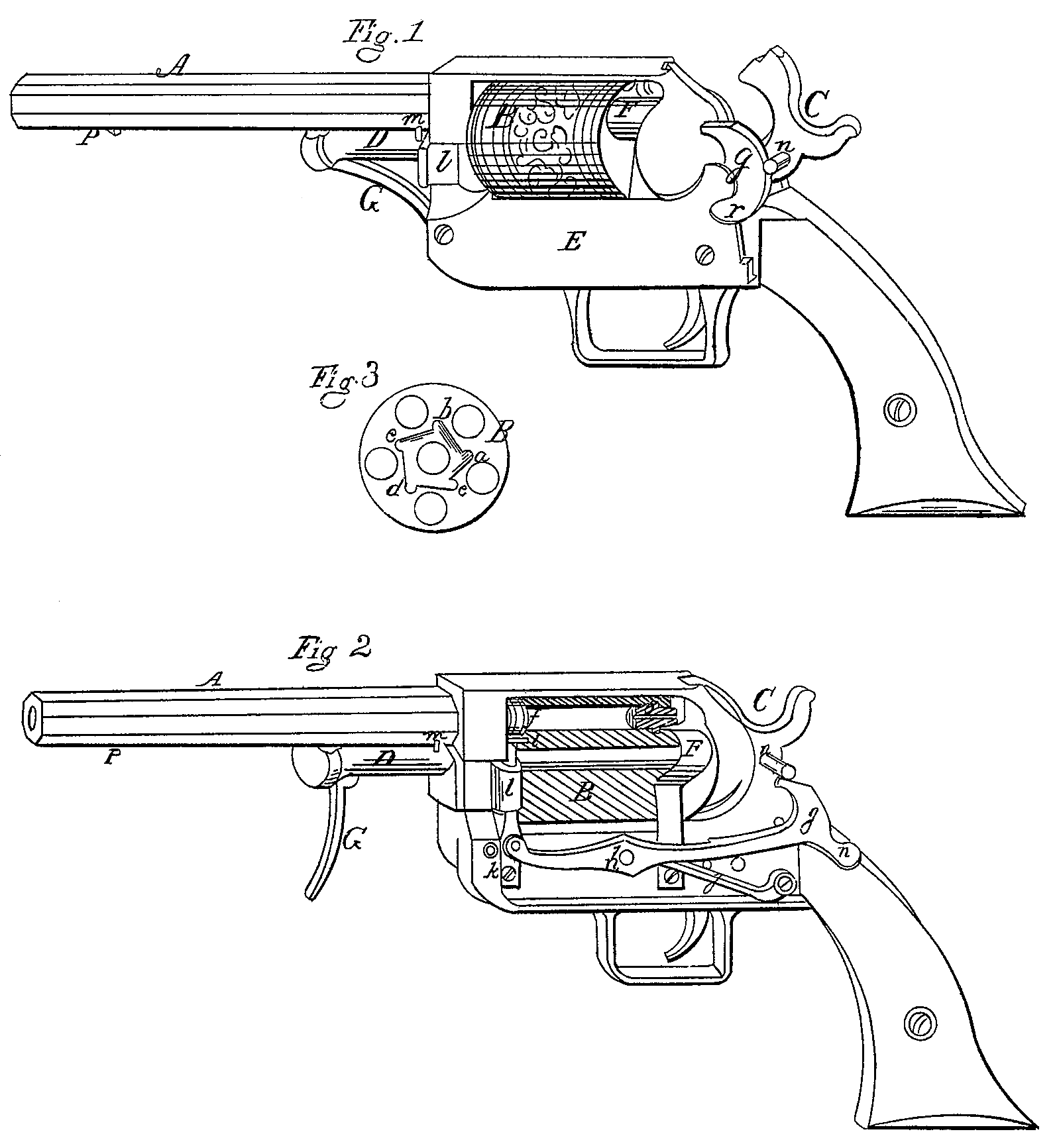
Figure 1 is a perspective view of a pistol when ready to revolve the cylinder and discharge it, showing the back end of the lever which serves to revolve the cylinder and also serves as a protection against accidental discharge. Fig. 2 is a perspective view of a longitudinal section of the same, showing the Whole of the apparatus which serves to revolve the cylinder and the spring-shield which covers and protects the caps from accidental ignition. Fig. 3 is a plan view of the front end of the cylinder, showing the form of the recess in which the lever moves and acts to revolve the cylinder.
My improvement consists in revolving the chambered cylinder by means of a jointed lever acting in recesses in the front end of the cylinder and worked by a thumb piece on the back or rear end of the lever by pressing it down with the thumb immediately before pulling the trigger; and in so constructing the back or rear end of the lever that it will form a complete protection against accidental discharge; and in the manner of constructing and locating the spring-shield to protect the caps which have not yet come up to the place to be acted on by the hammer from being accidentally ignited.
I make the barrel A, revolving cylinder B, hammer C, rod or mandrel D, the working parts of the lock, the trigger, &c., all in the usual ways, as shown in Figs. 2 and 1. In the front end of the cylinder B, I form a polygonal recess, as shown in Fig. 3, with as many angles or points a b c d e as there are chambers in the cylinder, and so arrange them that when the cylinder is revolved from one point to another, as from a to b, the chambers will be brought alternately in a line with the barrel A, as seen at f, Fig. 2. To revolve this cylinder I fit into the frame, under the plate E, a jointed lever, g h i, Fig. 2, which works on a fulcrum-pin at h, so that when the end g of the lever is depressed to the position shown in Fig. 2 the finger or end i, having acted in the recess, as at a, Fig. 3, will be elevated so as to revolve the cylinder, as from a to b, Fig. 3, or so as to bring the next succeeding chamber in a line with the barrel, as seen at f, Fig. 2, in which position the pressure of the lever will firmly lock the cylinder, where it must remain until the pistol is again cocked. When the hammer is drawn back to cock the pistol the spring i, acting upon the lever g h i, will elevate the back end, g, of the lever to the position seen at g, Fig. 1, and the front end, i, will descend along the inclined plane, as from b to a, Fig. 3, when the spring k, Fig. 2, will force the front end outward to the extreme point, as at a, Fig. 3, when the cylinder may again be revolved for the next discharge by again depressing the back end, g, of the lever to the position shown at g in Fig. 2.
The front end, i, of the jointed lever g h i is steadied in its position and guided in its operation by a guide or clasp, l, which is secured to the front end of the frame by the rod D, passing through it in such a manner that when the rod D is drawn back it is movable in the direction of the barrel sufficiently to remove the upper end, i, of the lever out of the recess a b c de, Fig. 3, (where it is stopped by the pin m, Figs. 1 and 2,) when it is desired to take out the cylinder, either to load the chambers or to put another cylinder in its place, which change may readily be made, so as to lose but little time in firing.
The lever g h i will be held in the position shown in Fig. 2, when the hammer C is resting on the cone or nipple, by means of the pin or projection in, Figs. I and 2, resting on the inclined plane near g, so that the cylinder cannot be revolved by any means whatever; and when the hammer is drawn back to the position of cocking, as shown in Fig. 1, the spring j will elevate the back end, g, of the lever to the position seen in Fig. 1, when the pin or projection in will rest against the curve on the back end of the lever, so that it will be impossible to discharge the pistol without first pressing down the back end, g, of the lever, thus affording a perfect protection against accidental discharge, even though the sear or the notch in the tumbler should entirely ?ail while the pistol was cocked.
To protect the caps from accidental ignition I fit a spring-shield, F, Figs. 1 and 2, curved in such a manner as to entirely cover the cap next lack of that on which the hammer is to strike. One edge of this shield rests on a slight projection or bead on the cone, as shown at o, Figs. 1 and 2, to prevent injuring or displacing the caps. This shield will also prevent the recoil of the cylinder while the finger or end i of the lever is descending along the inclined plane.
The cylinder is held in its place, ready to be revolved, by a rod or mandrel, D, in the usual way. This mandrel is secured in the position shown in Figs. 1 and 2 by a spring-catch (not seen) governed by the lever G, so that when the lever G is in the position seen in Fig. 2 the catch is released, so that the rod may be drawn out (until it is checked by the knob or stop p) so as to release the cylinder, when by moving the guide or clasp l out to the pin or stop in the cylinder may be taken out for loading or charging. When the cylinder B is loaded it is put into its place, (the hammer C having been drawn back,) the rod D is forced in and the lever G thrown against the frame, as seen in Fig. 1, where the spring-catch will hold it firmly, the guide l placed in the position seen in Fig. 2, (where it will be held by the rod D,) so that the point i of the lever will fall into the recess a b c de, and the plate E screwed on in its place. The whole will then be in the position and arranged as shown in Fig. 1, and ready to revolve the cylinder and discharge the pistol.
To revolve the cylinder, place the thumb of the right hand on the thumb-piece r of the lever and press it down as far as it can go— that is, to the position seen in Fig. 2— by which operation the cylinder B will be revolved to the proper position for discharging, when the trigger may be pulled in the usual way and the pistol discharged, (as the pin n will then pass over the inclined plane near g, as seen in Fig. 2;) but should the trigger be pulled too soon— that is, before the cylinder is fully revolved to its place— the pin n will strike the curve of the lever near g, as shown in Fig. 1, and thus prevent the hammer C from approaching the cap until the end of the lever is brought entirely down, so that the pin n will pass the inclined plane, as seen in Fig. 2, so that, if necessary, the hammer may be sustained wholly (when drawn back to the position of being cocked) by the pin n resting on the curve of the lever, as seen in Fig. 1, and the pistol be discharged by simply pressing down the end of the lever with the thumb, without reference to the tumbler, sear, or trigger, as neither is necessary.
The advantages of my improvement consist in revolving the cylinder by a lever independent of the operation of the hammer or trigger, which renders the machinery much less complicated, and therefore less liable to get out of repair, and much more easily repaired when necessary, on account of its simplicity; and in the perfect protection against accidental discharge afforded by the shape and position of the rear end of the lever combined with the pin in the hammer.
What I claim as my invention, and desire to secure by Letter’s Patent, is—
1. The combination of the independent lever g h i with the cylinder B, when so arranged that the cylinder may be revolved and locked without reference to or the use of either the hammer or trigger, and the whole is constructed and combined substantially as herein described and set forth.
2. The combination of the spring-shield F with the cones or nipples, when so arranged as to cover and protect the caps without any risk of injuring them or moving them out of place, and also serves to prevent the recoil of the cylinder, when constructed and combined substantially as herein described.
JEREMIAH PECK.
Witnesses:
Frederick. C. Orton.
Tr. Fitzgerald.