
US 10812
UNITED STATES PATENT OFFICE.
JOSIAH ELLS, OF PITTSBURG, PENNSYLVANIA.
IMPROVEMENT IN REVOLVING FIRE-ARMs.
Specification forming part of Letters Patent No. 10,812, dated April 25, 1854.
To all whom it may concern:
Be it known that I, Josiah Ells, of Pittsburg, in the county of Allegheny and State of Pennsylvania, have invented certain new and useful Improvements in Revolving-Breech Fire-Arms applicable to guns, rifles, and pistols; and I do hereby declare that the following is a full, clear, and exact description there of, reference being had to the annexed drawings, forming part of this specification, in which—
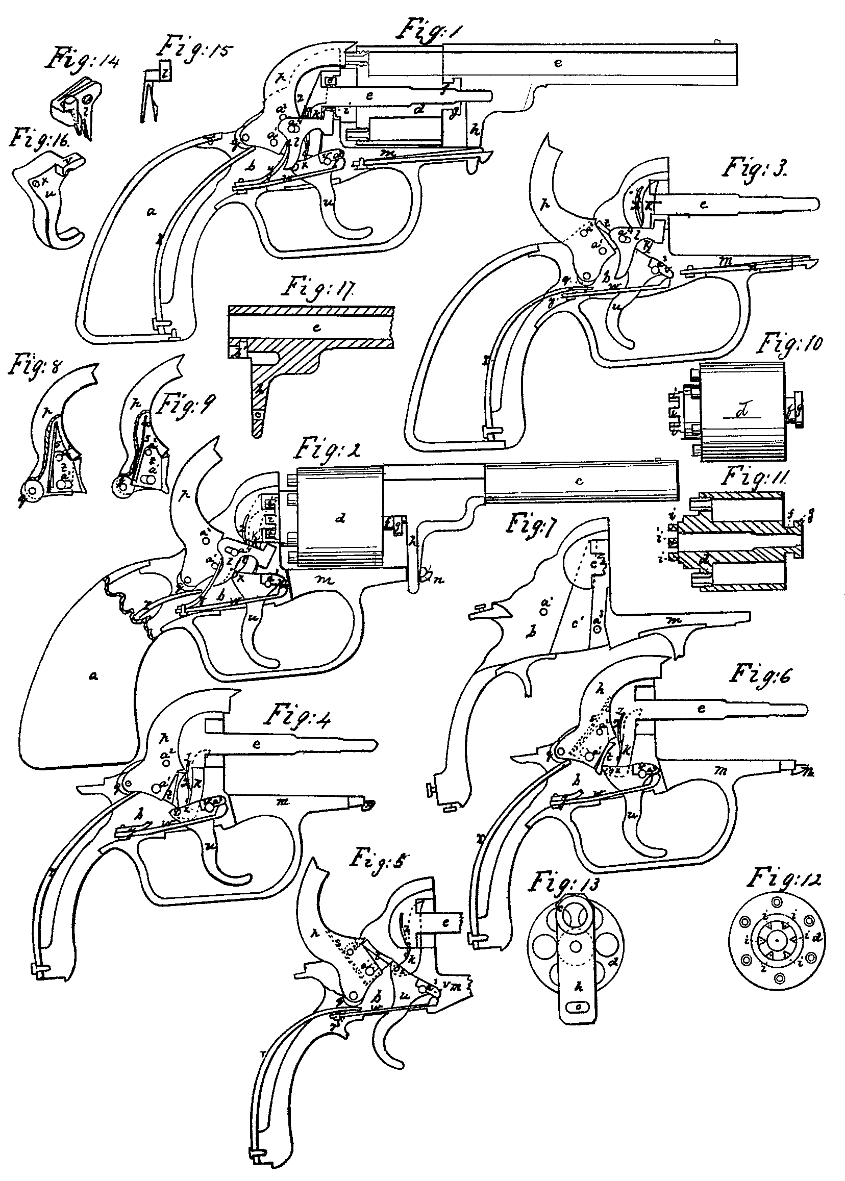
Figure 1 is a sectional side view of a pistol constructed with my improvements, a portion of the lock-plate being removed to exhibit the parts composing the lock, which are shown in their position before the pistol is cocked or fired. Fig. 2 is a side view of the pistol, showing the outside of the barrel and breech, and exhibiting the parts of the lock in their position when the trigger is pulled half-way back. Fig. 3 is a sectional view of the lock-frame, and exhibits the several parts of the lock in their position when the trigger is fully drawn back. Figs. 4, 5, and 6 are side views of the lock-frame, showing the several parts of the lock, excepting the spring-bolt l, which is removed to exhibit the other parts more clearly. In Fig. 4 the parts of the lock are in a state of rest be fore firing. In Fig. 5 the hammer is raised by the trigger, and is on the point of firing. In Fig. 6 the hammer has fallen to fire the pistol, and the trigger is in the act of regaining its position for the purpose of repeating the fire. Fig. 7 represents the lock-frame with all the parts of the lock removed, showing the position of the recess in which the finger k works. Fig. 8 represents the hammer, a part of which is removed to exhibit its vibrating tooth; and Fig. 9 is the same as Fig.8, excepting that the vibrating tooth is pressed back. Figs. 10, 11, 12, and 13 represent the revolving breech. Fig. 10 is a side view; Fig. 11, a longitudinal section through its axis. Fig. 12 is a view of the back end; and Fig. 13 is a view of the frontend, showing how much of the face of the breech is covered by the barrel. Fig.14 is a perspective view of the spring-bolt, and Fig. 15 is a plane side view of the same. Fig. 16 is a perspective view of the trigger, designed to show more clearly the shoulder on which its spring rests and the stud by which the spring-bolt is operated. Fig. 17 is a sectional view of the breech and of the barrel, designed to exhibit the shape and position of the recess which receives the tubular extension and collar of the breech.
The similar parts of the pistol are in the several figures referred to by the same letters.
My invention consists in connecting the barrel and rotating breech by means of a tubular extension and collar to the breech fitting into a corresponding recess in the barrel, which so inclose the spindle which carries the rotating chamber as to prevent its being fouled by the explosion of the powder; also, in the insertion into the hammer of a vibrating tooth, against which the trigger acts to raise the hammer, but which, when the hammer has fallen, recedes to permit the trigger to regain its position for repeated motion; also, in the use of a bracket and spring extending in front of the lock-plate for the purpose of connecting and locking the barrel and breech to the stock.
In the several drawings, a is the stock of the pistol. b is the lock-plate, which is made in the usual manner. c is the barrel. d is the revolving chambered breech.
From the lock-plate b extends in a suitable position and parallel to the axes of the barrel the spindle e, which passes through the rotating breech and extends, if desired, (though this is not necessary,) into the bracket of the barrel.
The rotating breech is made of the usual form of that part of repeating fire-arms, so far as relates to the chambers to receive the charge and the nipples for receiving the percussion caps; yet it differs materially by the addition to the lower end of the breech of a tubular extension, f, surrounded at the extremity by a circular collar, g.
In the bracket of the barrel, below the bore, is a recess, b’, of the exact shape of the upper half of the cylindrical extension and collar, so as to receive the collar readily and yet fit closely round it. (See Fig. 17, where the breech end of the barrel is shown in section to exhibit the position and shape of the recess.) The end of the barrel fits close up to the end of the rotating breech, so that the axis of the bore of the barrel and of each of the chambers of the breech, if brought round to the line of the barrel, will be in the same line exactly, the spindle passing through the exact center of the rotating breech. The collar and tubular extension of the rotating breech not only form a locking connection between the rotating breech and the barrel, but the collar, fitting closely into the recess, sustains the recoil of the breech after filing, which in ordinary repeating fire-arms is borne by that part of the lock-plate called the “recoil-shield.” The tubular extension and collar so effectually cover up the spindle which carries the rotating breech as to prevent its being fouled by the residuum of the gunpowder after firing, which is a great impediment to the successful action of the rotating breech, and makes it necessary for it and the spindle to be frequently cleaned. The form and construction of the rotating breech will be seen more clearly by reference to Figs. 10, 11, and 12.
At the extremity of the rotating breech are ratchets i i, &c., equal in number with the number of chambers in the breech, at equal distances apart, and with a space between each. These ratchets enter a recess in the lock-plate around the spindle, and it is against them that the finger k works to rotate the breech, and between them the head of the spring-bolt l passes to secure the rotating breech in its position during the discharge of the pistol, as hereinafter described.
Immediately beyond the recess in the barrel is the bracket l, which extends down at right angles to the barrel as far as the extension m of the lock-plate. This extension of the lock-plate projects just so far that its extremity passes through a small hole in the bracket of the band.
In a recess or groove in the under side of the extension m is a spring, n, with a head at its extremity which projects beyond the extension m far enough to catch on the outer side of the hole o in the lower part of the bracket, h of the barrel, (see Figs. 13 and 17.) and thus securely attach the barrel and rotating breech to the lock-frame. This arrangement secures the speedy attachment and removal of the barrel and breech. To remove them it is only necessary to grasp the barrel in the hand, and with the thumb to press up the head of the spring, when by pulling the barrel from the stock a separation at once ensues.
It now remains to explain the construction and operation of the several parts of the lock. These are shown in a state of rest be fore firing in Fig. 1. p is the hammer, which turns on the hammer-pin a’. At the heel of the hammer is a friction wheel or roller, q, against which the end of the mainspring r works. The mainspring r is attached to the lower extremity of the lock-plate, passing up through the hollow part of the stock of the pistol. The mainspring is designed to force the hammer, after it is released from the trigger, down against the nipple of the breech to explode the percussion-cap. The hammer is represented in Fig. 1 as lying in its recess in the upper part of the lock-plate, the space between the dotted lines and the under side of the hammer showing the depth of the recess, its width being such as to allow of the easy play of the hammer. In the lower part of the hammer, and extending nearly to its heel, is a slit to receive a vibrating tooth, t. (See Figs. 8 and 9.) This vibrating tooth is hung in the hammer on the hinge-pin a^2, and a slot in the lower part of the tooth, through which the hammer-pin a’ passes, prevents the hammer-pin interfering with its action. The length of the slot also determines the extent to which the vibrating tooth projects from the hammer. One end of the slot, pressing against the hammer-pin a, sustains the pressure of the trigger when the hammer is being raised, as will be more clearly seen hereinafter. In the slit in the hammer and behind the vibrating tooth t is a slight spring, s, which presses the vibrating tooth forward whenever it is released from the back-stroke of the trigger. The trigger u, of the shape shown in Fig. 16, is hung on the trigger-pin a^3. Immediately in front of this pin is a shoulder, v, in which rests the end of the spring w, which is placed in and secured to the lock-plate, as shown in the several Figs. 1 to 6. This trigger-spring w enables the trigger to recover its position after being pulled back. The position of the point of the trigger before firing, in relation to the hammer and vibrating tooth, is shown clearly in Fig. 4. The toe of the vibrating tooth rests on the trigger near its points. As the trigger is drawn back the point, pressing against the under side of the vibrating tooth, raises the hammer to the point of “full-cock,” (shown in Fig. 5,) the hammer as it rises pressing down the mainspring r. When the trigger and hammer are in the position shown in Fig. 5 the slightest touch of the trigger causes its point to pass the extreme point of the toe of the vibrating tooth, and the hammer immediately descends, striking forcibly against the end of the nipple on the rotating breech and firing the pistol. So soon as the pressure of a person’s finger is removed from the trigger the spring w causes it to recover its first position. In doing this it must pass on its back-stroke the end of the vibrating tooth, which yields to the pressure of the point of the trigger, as shown in Fig. 6, the vibrating tooth receding, as shown in Fig. 9, and the trigger regains its first position and is ready for repeating the operation of firing. The arrangement of the position of the hammer-pin a’, the trigger-pin a^3, and the hinge-pin a^2 of the vibrating tooth is such as to be peculiarly adapted to produce ease in firing.
In repeating fire-arms as ordinarily constructed the mainspring is so arranged that the greatest amount of force is required in raising the trigger as it approaches the point of full-cock, and when the hammer is descending the spring acts against it so that its greatest force is at the beginning of the downward stroke, and its force gradually diminishing as it approaches the nipple in the breech. The reverse of this should be the case, and I have attained this object by my arrangement. As the hammer rises, the point of bearing of the mainspring on the heel of the hammer is brought gradually more in a perpendicular line with the center or turning point of the hammer, while the effective power or leverage of the trigger to overcome the pressure of the spring is gradually diminished, and at the point of full-cock the center-pin a’ of the hammer and the point of pressure of the spring are brought almost in a perpendicular line. It is evident that if the point of pressure of the spring were brought immediately under the center-pin of the hammer, the hammer would have no tendency to fall, and the nearer it approaches to that point the less does the force required to overcome the pressure of the mainspring become. So, also, as the hammer falls the effective leverage of the mainspring increases and the hammer has its greatest force when it reaches the percussion-cap on the nipple of the breech.
When the pistol has been fired and the trigger and other parts have resumed their first position it is necessary that in raising the hammer again by pulling the trigger the breech should be turned so far as to bring the next loaded chamber in a line with the barrel. This is effected by the finger k, which is connected With the trigger by a pin projecting from its side at the lower extremity, and which enters into a corresponding circular hole in the side of the trigger, near its point immediately opposite the stud x. The finger k lies in the recess c’ in one side of the lock-plate. (Shown in Fig. 7.) A spring, z, on the back of the finger presses against the wall of the recess and keeps the finger pressed forward. The recess extends, as shown in Fig. 7 by dotted lines, so far as to open into and connect with the circular recess around the spindle e, into which the ratchets i i, &c., on the rotating breech enter. When the trigger is in the position shown in Figs. 1 and 4 it does not at all interfere with the ratchets; but as it rises to the position shown in Fig. 5 on entering the circular recess around the spindle it comes in contact with one of the ratchets, and on attaining the point when the pistol is at full-cock it has turned the breech round so as to bring another chamber to the exact line of the bore of the barrel, where it is retained, as hereinafter explained, until the pistol is fired and the trigger is again drawn back to repeat the fire. By the falling of the trigger after firing, the finger is withdrawn and resumes its first position.
The spring-bolt (see Figs. 14 and 15) is designed to lock the rotating breech in its proper position during firing, and is so constructed and arranged as to release the breech and allow of its rotating so soon as the finger k comes in contact with one of the ratchets i. In Fig. 14 that side of the spring-bolt l is turned toward the eye which is concealed from view in Figs. 1, 2, and 3. This spring-bolt is attached to the lock-plate by a pin, a^4, (see Fig. 1) which passes through the slot or pin-hole in the side of the bolt. (Seen in Fig. 14.) The center part of this bolt is composed of two leaves or springs, one of which (nearest to the eye in Fig. 1) rests against one side of the lock-plate. One edge of the other leaf rests against the stud x on the point of the trigger, as seen in Fig. 1. As the trigger is drawn back the point of the trigger rises, and the stud, still pressing against the edge of the inner leaf of the spring-bolt, turns it on its center-pin a^4 so far as to release the head of the bolt from the position which it occupies in Fig. 1, where it is represented as entering into the recess around the spindle e, and passing between two of the ratchets i i on the neck of the rotating breech, thus locking it in its place. The position then assumed by the head of the spring-bolt l is shown in Fig. 2, where it is drawn back so as to release the ratchet and allow the breech to rotate. In this Fig. 2 it will be seen that just as the head of the spring-bolt is cleared from the ratchet the finger k is coming in contact with the ratchet i’ in the circular recess. Until the finger k has risen so far as to turn the rotating breech the stud a retains its position on the edge of the leaf of the spring against which it rests; but so soon as the breech is rotated the stud reaches a point on the edge of the leaf of the spring where the edge of the leaf is beveled or chamfered, (see Figs. 14 and 15, and the dotted lines on the spring-bolt in Fig. 2,) and becomes so thin that the stud slips over onto the side of the leaf of the spring and passes round the projection. (See Fig. 14.) The spring y, pressing on the back of the spring-bolt, forces it up to its place again, locking the rotating breech, before the trigger has risen far enough to release the hammer and fire the pistol. The trigger then falls back to its first position, and in so doing the stud passes over the side of the leaf of the spring, which yields sidewise to allow it to pass without disturbing its position of locking the ratchets, and when the trigger has entirely recovered its first position the stud x passes off the side of the leaf of the spring and resumes its position on the edge, as at first.
It is manifest that the pistol may be loaded without removing the rotating breech or barrel, for by a slight pull of the trigger the spring-bolt l may be unlocked from the ratchet, and the breech can then be freely turned (when the parts are in the position shown in Fig. 2) by hand, and the chambers in the breech successively loaded, as will be seen by Fig. 13, where, in a breech of six chambers, two of them, one on each side of the barrel, are entirely clear, and may be changed without difficulty and the breech turned round till all are loaded.
I disclaim originality in the combining of a rotating chambered breech with a barrel and lock only in the particular manner I have set forth. Neither do I use what is called the recoil-shield as such, the collar upon the extension sustaining or preventing the actual recoil of the breech.
I also disclaim originality in the use of the vibrating tooth and the spring in the hammer.
Having thus described my improvements in rotating-breech fire-arms, what I claim as my invention, and desire to secure by Letters Patent, is—
1. The extension on the fore part of the rotating chambered breech as a prevention of the fouling of the spindle by the smoke in firing, and also as a means of connecting and locking the breech with the barrel, as herein set forth.
2. The connecting and locking the barrel and breech to the lock by means of a bracket and spring extending in front of the lock-plate, in the manner described.
JOSIAH ELLS.
Witnesses:
Wm. N. Howard,
Geo. H. Lee.