
US 52248
UNITED STATES PATENT OFFICE.
HENRY S. JOSSELYN, OF ROXBURY, MASSACHUSETTS, ASSIGNOR TO HIMSELF AND W. E. WOODWARD, OF SAME PLACE.
IMPROVEMENT IN REVOLVING FIRE-ARMS.
Specification forming part of Letters Patent No. 52,248, dated January 23, 1866.
To all whom it may concern:
Be it known that I, HENRY S. JOSSELYN, of Roxbury, in the county of Norfolk and State of Massachusetts, have invented a new and useful Improvement in Fire-Arms; and I do hereby declare that the following is a full, clear, and exact description thereof, which will enable others skilled in the art to make and use the same, reference being had to the accompanying drawings, forming part of this specification, in which–
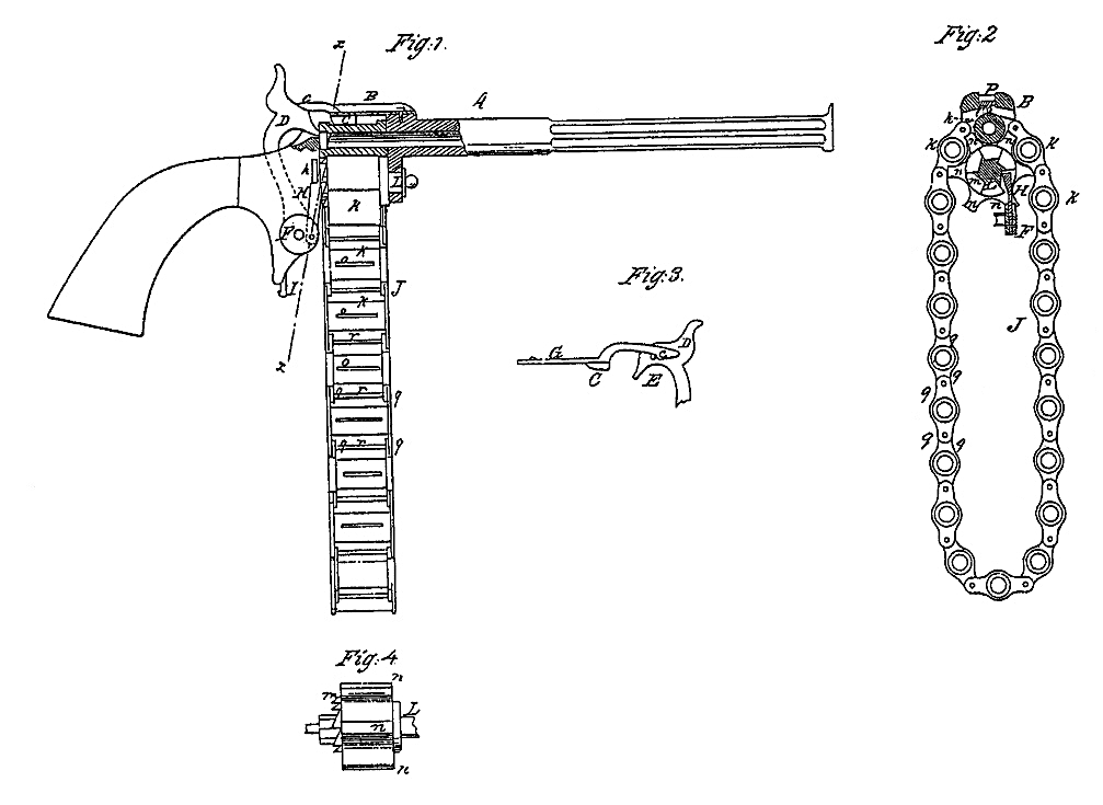
Figure 1 is a side view of a fire-arm made according to my invention, the receiver and part of the barrel being shown in section. Fig. 2 is a cross-section on the line x of Fig. 1. Fig. 3 is a detailed view of the device which holds the uppermost chamber stationary, and of part of the hammer. Fig. 4 is a side view of the shaft which carries the chain of chambers.
This invention consists in providing a fire-arm with a series of cartridge-chambers connected so as to form an endless chain, which is carried upon a shaft whose rotation is effected by the cocking of the hammer.
A designates the barrel of a fire-arm, B its receiver, and D its hammer. F is a crank plate fixed on one end of the axis of the hammer. This crank-plate carries a pawl, H, that extends upward therefrom alongside of the receiver, and acts upon a ratchet cut on the shaft or axis L by reaching such ratchet through a vertical slot, h, made in the receiver. The trigger of the piece is seen at I.
The shaft or axis L revolves in bearings in the under part of the receiver, directly beneath its center, and in line with the barrel A. It has a ratchet, m, formed on it near its hinder end, which ratchet revolves opposite the vertical slot h, so as to be acted upon by the pawl H.
The axis I has on its periphery, at about the middle of its length, a series of arms, n, six in number in this example, and at equal distances apart. These arms are of such a length and thickness as that they will fit between adjacent chambers of the chain, as shown in the drawings.
The chain J is here composed of twenty cartridge-chambers, K, which have lugs q extending from opposite sides at each end, said lugs being hinged on rods r, that extend from the lugs of one end to those of the other end between each chamber, as seen in Fig. 1. The spaces which separate the several claimbers are such as will enable the arms or sprockets n of the axis to articulate in the spaces as the chain is brought around, and the chain is by this means made to move with certainty and steadiness. Each clamber K has, on the outer portion of its periphery, a groove, o, parallel with its axis and midway between the lugs q.
When one of the chambers is in place in the receiver, as shown in Fig. 2, it is locked by the spring-latch C, which plays in a slot, P, cut through tle top of the receiver. This latch consists of a horizontal body whose forward end is fastened to the receiver by a screw, and of a vertical tooth that projects downwardly from its back end in line with the groove of such one of the chambers K as is for the time in the receiver.
The position of the axis L, the capacity of the receiver, and the diameter of the chambers K, are determined with reference to the bore of the barrel A, so that any chamber while in the receiver and locked by the latch C will have its bore in exact agreement with the bore of the barrel.
Fig. 3 is a detailed view of the latch C and of so much of the hammer as is necessary to show how the latch is operated.
The body G of the latch constitutes its . spring, the tendency of which is to force the vertical part C downward into the receiver. The body G of the latch has an arm, c, extending backward so as to lie alongside of the hammer when the latter is down.
The lower edge of the arm c, at its end, has an inclination, which swells as it runs forward and then suddenly terminates, thereby forming a dull hook-shaped comb. A pin, E, projects from that side of the hammer along which the arm c extends, and the operation of the pin and hammer is to raise the latch out of engagement with the grooves O of the cartridge-chambers whenever the hammer falls, and also when it is drawn back for cocking, the pin E always being beneath the said arm c. At the time the hammer is drawn back the crank-plate F on its axis is made to turn and carry its pawl H upward so as to act upon the ratchet m, thereby giving rotary motion to the axis L, which, through its arms or sprockets n, moves the chain of cartridge-chambers. This movement is from the center of one chamber K. to the next chamber.
The commencement of the movement is not impeded by the latch, because the latter is, at that time, raised by the pin E of the hammer, and its termination is not impeded by the latch, because its body G, being elastic, allows the latch to be raised when the periphery of the advancing cartridge-chamber strikes against it.
All the chambers are to be kept supplied with cartridges, and when one of them reaches the highest position in the receiver, as shown in Fig. 2, it is ready to be discharged merely by bringing the hammer down.
The chambers and hammer are adapted for the use of cartridges which have around their back ends a flange filled with fulminating material, and which flange is reached by the hammer through a slot in the back part of the receiver in line with the slot P. As fast as the cartridges are fixed the chambers are revolved, and the shells of the cartridges are then removed and fresh cartridges placed in them.
I do not claim, broadly, an endless chain of cartridge-chambers, nor do I claim revolving the chain by a pawl in the act of cocking the hammer; nor do I claim, broadly, locking the cartridge-chamber by means of a spring-latch but
I claim–
1. In fire-arms, an endless chain of cartridge chambers arranged to rotate upon an axis which is parallel with the bore of the barrel and which has a series of sprockets that engage with the interspaces of the chain, substantially as shown.
2. In combination, the endless chain J of cartridge-chambers, the spring-latch C with its arm c, and the pin E of the hanmer, substantially as shown.
The above specification of my invention signed by me.
H. S. JOSSEYN.
Witnesses:
FAIRFIELD GILBERT,
GEORGE. H. BRACKETT.