
US 37551
UNITED STATES PATENT OFFICE.
FRANK P. SLOCUM, OF BROOKLYN, NEW YORK, ASSIGNOR TO SAMUEL W. SLOCUM, OF SAME PLACE.
IMPROVEMENT IN REVOLVING FIRE-ARMS.
Specification forming part of Letters Patent No. 37,551, dated January 27, 1863.
To all whom it may concern:
Be it known that I, Frank. P. Slocum, of the city of Brooklyn, in the county of Kings and State of New York, have invented a new and useful Improvement in Revolving Fire-Arms; and I hereby declare that the following is a full, clear, and exact description of the same, reference being had to the accompanying drawings, forming part of this specification, in which—
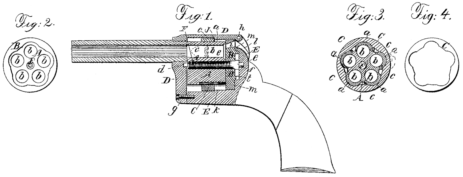
Figure 1 is a central longitudinal vertical section of a pistol constructed according to my invention. Fig. 2 is a front view of the cylinder. Fig. 3 is a transverse section of the same. Fig. 4 is a front view of the ring which encircles the cylinder to keep the chambers closed.
Similar letters of reference indicate corresponding parts in the several figures.
This invention has for its object to provide for the loading of revolving fire-arms with flanged metallic cartridges without having the chambers extend right through the cylinder to the rear thereof; and to this end it consists, first, in constructing the several chambers with longitudinal divisions and with a portion of each movable, like a lid, to admit the cartridges sidewise; secondly, in the use, in combination with the so-constructed cylinder, of a ring encircling the said cylinder and capable of sliding on and of the movable or lid-like portions of the several chambers for the purposes of securing them in a closed position when loaded, and of permitting them to be opened for loading and for the removal of the discharged cartridge-cases; thirdly, in the construction of the cylinder-frame with one or more internal shoulders to serve as stops to the aforesaid ring.
To enable. others skilled in the manufacture and use of fire-arms to make and use my invention, I will proceed to describe its construction and operation.
The cylinder is composed of two principal pieces, A and B, and the lids a a of the several chambers b b. The chambers are bored right through the portion A, which is of sufficient length, and the piece B, consisting of a stout disk, is secured close to the rear of A, to which it forms a breech, closing the chambers at the rear. The front portion of each chamber has its whole circumference formed of the piece A; but the greater portion of its length is formed half in the piece A and half composed of its lid b, which is of semi-cylindrical form and fitted into the piece A and close up to the piece B, the chamber being thus divided longitudinally in a plane passing through the axis of its bore. The lids b b are each hinged on one side by a hinge-joint, c, to the portion A of the cylinder to permit them to open, as shown in red outline in Fig. 3, for the insertion of the cartridges sidewise into the chambers.
C is the ring which encircles the cylinder for the purpose of securing the several lids b b in a closed condition, having its interior of a form shown in Fig. 4, to fit snugly round the chambered portion of the cylinder, and to the exterior of the lids b b, and being of a width corresponding with, or not greater than, the length of the portion of the cylinder in front of the lids, the exterior of which is made to conform to that of the exterior of the lids, so that the ring may slide freely upon it, as well as upon the lids, in a direction lengthwise of the cylinder. By sliding this ring from the lids onto the portion of the cylinder in front of them the lids, being made of proper form to be caught by the thumb or finger, are allowed to be opened in the manner indicated by red outline to permit the insertion of cartridges into the chambers or the withdrawal of the discharged cartridge-cases therefrom. When new cartridges have been inserted into the chambers the lids are closed and the ring slid back over them to secure them.
The cylinder is represented as having the axis-pin F Secured firmly in it, being constructed with pivots or journals d e at is front and rear ends to fit into suitable bearings provided for their reception in the front and rear of the frame D E. This mode of applying the axis pin enables it to serve the purpose of securing the two pieces A and B of the cylinder firmly together, for which purpose it is made with a male screw-thread upon its front part to screw into a female screw-thread provided in the piece A, and with a square head, f, close to its rear journal for the reception of a wrench to screw it up tightly against the rear of the piece B, through which it is inserted into A. The two pieces A and B may, however, be secured together by two or more screws independent of the axis-pin. It is only for convenience of construction that the cylinder is composed of separate pieces, A and B, as the breech part might be made of the same piece with the chambered portion. The hammer strikes the cartridges in the several chambers through openings i in the breech of the cylinder.
The frame D E is represented as formed of two pieces, of which the piece D constitutes the front and upper portions, and the piece E the rear and lower portions, the said pieces being secured together by a screw, g, at the lower front corner, and a pin, h, inserted transversely through a mortise-and-tenon joint at the rear upper corner. This construction permits the insertion of the cylinder after the axis pin has been secured in it.
In the interior of the upper portion of the frame there is provided a shoulder, j, and in the interior of the lower portion a shoulder, k, to serve as stops to the ring C when the latter has arrived at about the middle of the length of the lids of the chambers in sliding back over them, that being the best position for securing the said lids. One of these stops may be sufficient.
The construction of the cylinder with lids opening to admit sidewise metallic cartridges carrying their own priming, and with a closed breech, allows the whole of that portion of the rear end of the cylinder outside of the revolving ratchet l to be made to present a flush face and to fit closely against the recoil-shield m, by which means the cylinder is better sustained against recoil.
Instead of arranging the lids or movable portions of the chambers to work on hinge-joints, they may be arranged to open with a sliding movement parallel with the axis of the cylinder.
The dog by which the rotation of the cylinder is stopped, and by which the cylinder is locked with the several chambers in line with the bore of the barrel, may be applied to act in notches provided in the ring C, and be so made to secure or aid in securing the said ring in position to secure the lids a a.
What I claim as my invention, and desire to secure by Letters Patent, is—
1. The cylinder constructed with lids b b to its several chambers, opening in such manner as to permit the cartridges to be introduced and the discharged cartridge-cases to be taken out sidewise, and with a closed or solid breech, substantially as herein specified.
2. The ring C, applied in combination with the cylinder and the lids a a of the chambers, substantially as and for the purpose herein specified.
3. The combination, with the ring C, of one or more stops, j k, in the frame, substantially as and for the purpose herein specified.
FRANK. P. SLOCUM.
Witnesses:
Danl. Robertson,
M. S. Partridge.