
US 41857
UNITED STATES PATENT OFFICE
WILLIAM PALMER, OF NEW YORK, N. Y.
IMPROVEMENT IN REVOLVING FIRE-ARMS.
Specification forming part of Letters Patent No. 41,857, dated March 8, 1864.
To all whom it may concern:
Be it known that I, WILLIAM PALMER, of the city and State of New York, have invented, made, and applied to use certain new and useful Improvements in Revolving Fire-Arms; and I do hereby declare that the following is a full, clear, and exact description of my said invention, reference being had to the annexed drawings, making part of this specification, wherein–
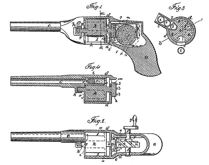
Figure 1 is a vertical longitudinal section of my arm. Fig. 2 is a plan with the case over the works removed. Fig. 3 is a cross-section at the line a a, and Fig. 4 is a partial sectional plan at the line b b.
Similar marks of reference denote the same parts.
Short sections of a barrel, or what I term “chambers,” have before been constructed and provided with cartridges to be brought at the rear of and on line with the barrel, and held there while discharged. Such chambers have been either presented to the rear of the barrel upon a revolving plate, to which they were attached, or by a reciprocating device that conveyed such chambers successively from a hopper to the rear of the barrel.
The nature of my invention consists, first, in the employment of a carrier intermittently revolved by suitable automatic mechanism, and presenting one of said loaded chambers at the rear of the barrel, pausing while the charge is fired, then proceeding on by said mechanism, and presenting another chamber on the line of the barrel, the previous discharged chamber being allowed to drop out of the said revolving carrier; second, incombining with said revolving carrier a hopper slide or opening so located on a plane parallel or nearly parallel to the axis of said revolving carrier that the said chambers shall by their own gravity descend into the grooves provided in said revolving carrier as such grooves are successively presented for the reception of said chambers; third, in combining with the said revolving carrier a shield or casing to retain the said chambers in the revolving carrier from the point at which they drop from the said hopper slide or opening until they have been fired, after which said chambers are allowed to drop away by their own gravity; fourth, in the employment of a revolving cam, in combination with said rotary carrier, said cam being so formed as to allow the necessary pause for the discharge of each chamber as brought opposite to the barrel, said cam also acting to hold the carrier and the chamber, so that the chamber is on the line of the barrel when fired; fifth, in the employment of automatic mechanism to press the chambers to the rear end of the barrel after being brought to line with the barrel by the aforesaid rotary carrier, so as to prevent the escape of gases, &c.; sixth, in the combination, with a detached section of a barrel or chamber, of a metallic cartridge so formed that the metallic case of the said cartridge enters the rear end of the barrel when pressed forward, as aforesaid; seventh, in constructing the mechanism that rotates the carrier in such a manner that a hammer is liberated to explode detonating powder and fire the piece at the time the said carrier is stationary, and then recock the hammer before the carrier commences again to move, the rotary automatic mechanism giving these relative movements to the hammer, and the carrier being unchecked in its revolution; eighth, in the mechanism employed for giving end motion to said carrier; ninth, in the means for moving the chambers with the carrier in its endwise action; tenth, in the mechanism for revolving the carrier.
In the drawing, c is a barrel of any desired size, either rifled or plain. This is to be connected with the mechanism of the gun by the metallic case d, which is formed of a size and shape adapted to the parts; and my arm may be provided with a stock, e, adapted to be grasped by the hand or placed against the shoulder, although my arm was originally designed for and especially adapted to a gun set on a rest or swivel and guided with one hand and revolved with the other, while the chambers are separately placed in by an attendant; or three or more attendants can be employed with such a gun–one to revolve the mechanism, a second to aim and guide the gun, while one or more supply the same with the detached chambers.
f is a short cross-shaft, with a crank, g, at the end, or other mechanism by which a rotary movement is given to the said shaft f. h is the axis of the revolving carrier k, and i i are the chambers, l is a slide opening or hopper so located that the chambers i i can be supplied through the same, and pass, by their gravity, into the grooves 1 1 1 of the rotary carrier k as the said carrier is revolved. The case d, surrounding the rotary carrier, acts as a shield to keep the chambers i i properly in the grooves 1 1 until after they have been fired, and an opening at 2, or the stopping of said shield, allows the chambers to fall out after being fired.
In order to revolve the carrier k, I employ the disk m, with the pins or projections 3 3. There should be twice as many pins as there are grooves 1 1 in the rotary carrier; and n is a cam on the shaft f, that is the thickness corresponding to the distance between two of said pins 3 3, except at a portion of its periphery, where diagonal grooves 4 and 5 are provided, which, as the cam n is revolved, take successively two of the said pins 3 3, passing them to the other side of the cam, hence turning the rotary carrier the amount necessary to bring an other chamber, i, on line with the barrel, and the edges of this cam n and the respective pins 3 3, one on each side, hold the said rotary carrier and the chamber i on line with the barrel with great precision; and the revolution of the said cam n can be continuous, although the carrier is by this mechanism allowed to pause while the piece is being fired.
In order to press the chambers i i up against the rear end of the barrel, I also make use of the can n, said cam being larger in diameter at the part which comes in contact with the disk m after the carrier has been turned, (by the grooves 4 and 5.) Thereby the said disk, carrier, and chambers are all pressed forward, and so held to make a tight joint between the chamber i and the rear end of the barrel while being fired by the hammer o. This hammer o is on the axis or centerpin, 6, and is fitted with a mainspring, 7, and the cam p on the shaft f acts on the tail 8 of the hammer to cock and keep the same cocked, except when the cam turns free from said tail 8, as shown by dotted lines in Fig. 1, when the piece is discharged by the hammer striking any suitable cap or detonating material.
In order to relieve the chambers i from the pressure against the rear end of the barrel, I employ the bridle-piece q, that passes from the rear of the cam n to the front of the disk m, and the cam in its revolution, relieving from said disk m, and taking against this bridle-piece q, draws the carrier and chambers back, as seen in redlines, Fig.1. A ring, 9, rising slightly above the bottom of the grooves 1 1, and attached to the said carrier k, taking against the front end of the chamber i, insures its retraction from the rear end of the barrel with the carrier.
The form of chamber i may be that of a cavity to receive powder and ball, with a nipple for a cap; but prefer the construction shown, in which a cylinder, i, open at both ends, is employed to receive the cartridge r, formed with a metallic case (containing fulminating powder at the ring-base, and containing the ball with grease in the said case) in front of the ball, as shown, and also set forth in Letters Patent granted to me July 23, 1861. This metallic case of the cartridge enters within the rear end of the barrel, and the rear end of the barrel sets into a conical recess in the forward end of the chamber i. With this character of cartridge, it is necessary to have the rear end of the grooves 1 1 closed by the recoil-plate 10, that should be formed solid with the revolving carrier, only being provided with an opening for the passage of the pointed hammer o.
The operation of my arm as a whole will be apparent from the foregoing, and will not require repetition, and I need only remark that the size and mode of forming and putting the respective parts together must depend upon the character and size of ball to be fired and the particular mode in which the piece is to be used in warfare.
Should a cartridge and chamber i be misplaced in the hopper l, and so pass into the rotary carrier, it may become necessary to reverse the movement of the crank g and shaft f to turn the cartridge and chamber back out effect which it is necessary that the hammer-tail 8 should be depressed to clear the cam p. A small link may for this purpose depend from the hammer-tail through an opening in the casing, and be drawn down by hand.
What I claim, and desire to secure by Letters Patent, is–
1. The employment of a grooved carrier, k, intermittently revolved by automatic mechanism, for presenting a chamber containing the charge to be fired to the rear end of the barrel and holding the same in place while being fired, as set forth.
2. I claim a hopper slide or opening, l, combined with said revolving carrier, when such hopper slide or opening is so located that the chambers placed therein descend into the said carrier by gravity, as set forth.
3. I claim a shield, d, in combination with said rotary carrier k and hopper slide or opening l, when said shield extends from the base of the hopper slide or opening l to the point at which the chamber i is brought into line with the barrel for firing, as specified.
4, I claim a revolving cam, n, in combination with the rotary carrier k, for giving progress ive motion to said carrier and allowing a pause while the piece is being fired, as set forth.
5. I claim the employment of automatic mechanism to press the chambers to the rear of the barrel and then withdraw the same, in combination with the rotary carrier, also moved by automatic mechanism, so that the motions are in unison, as set forth.
6. I claim the metallic-case cartridge r, formed and acting as specified, in combination with the detached chambers i, receiving the same, as specified.
7. I claim the combination of the rotary carrier k, cams n and p, and hammer o, in the manner specified, the parts being so formed and timed that the motions are harmonious, for the purposes and as set forth.
8. I claim the bridle-piece q, in combination with the cam n and the rotary carrier k, for drawing back the chambers i i and the rotary carrier, as specified.
9. I claim the ring 9, or its equivalent, in combination with the rotary carrier, for withdrawing the chamber i i as the carrier is moved, as set forth.
10. I claim the disk m and its pins 3 3, in combination with the cam n and its grooves 4 and 5, for the purposes and as specified.
In witness whereof I have hereunto set my signature this 30th day of September, 1861.
WM. PALMER.