
US 40687
UNITED STATES PATENT OFFICE.
EDMUND H. GRAHAM, OF YONKERS, NEW YORK,
IMPROVEMENT IN REVOLVING FIRE-ARMS.
Specification forming part of Letters Patent No. 40,687, dated November 24, 1863.
To all whom it may concern:
Be it known that I, EDMUND H. GRAHAM, of Yonkers, in the county of Westchester and State of New York, have invented a new and useful Improvement in Revolving-Cylinder Fire-Arms; and I do hereby declare that the following is a full, clear, and exact description of the same, reference being had to the accompanying drawings, forming part of this specification, in which–
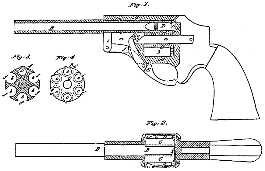
Figure 1, is a central longitudinal vertical section of a pistol constructed according to my invention, omitting the lock and other parts not necessary to illustrate the improvement, Fig.2 is a top view of the same, with the frame in section Fig. 3 is a transverse section of the cylinder and barrels. Fig. 4 is a back view of the same.
Similar letters of reference indicate corresponding parts in the several figures.
This invention consists in a sliding barrel so combined with a revolving cylinder as to slide longitudinally into and from the cylinder, and that each charge, while being fired, is contained in the barrel itself, the rear portion of the barrel forming the only chamber of the arm.
It also consists in certain mechanism for producing the longitudinal movement of the barrel, and, further, in giving the axis-pin of a revolving fire-arm a longitudinal movement, which may be instrumental in cocking the hammer.
To enable others skilled in the art to make and use my invention, I will proceed to describe its construction and operation.
A is the frame of the arm; B, the barrel; C, the cylinder. The cylinder is arranged to rotate upon an axis-pin, a, parallel with the barrel, in the usual manner, but, instead of being constructed with chambers of a size to receive the cartridges snugly within them, is made with a series of cylindrical cavities, b b, arranged parallel with its axis, but of considerably larger diameter than the exteriors of the cartridges, and open along the outside of the cylinder, as shown at f f Fig. 3. At the lack of each of these cavities there is provided in the cylinder a smaller circular opening, c, concentric with the cavity, such openings being of a size for the cartridges to fit snugly within them, and these openings are also open in the sides of the cylinder, as shown at c’ in Fig. 4.
The cartridges D, Fig.1, which I propose to employ are what are known as “fixed ammunition,” having metallic shells, and a fulminate priming being contained in a flange, e, projecting outwardly from the cylindrical portion of the shell, and these cartridges are to be inserted in to the cylinder from the rear end, such insertion being permitted either by taking out the cylinder from the frame, by constructing the frame to open with a hinge, or by providing in the recoil-shield d an opening through which the cartridges can be inserted one at a time. There is a sufficient space left between the rear end of the cylinder and the recoil-shield to receive the flanges or heads of the cartridges.
The barrel B has the rear portion of its exterior turned aud finished to fit snugly but easily into the cylindrical cavities b b of the cylinder, and into a hole, h, bored through the front of the frame for its reception, the said hole being in such position that by the revolution of the cylinder the several cavities may be brought one at a time exactly opposite to it, for the purpose of allowing the barrel to slide into the cylinder. The rear end of the barrel is made to fit up against the backs of cavities b b and provided with a lip, g, on its upper side, to enter the open spaces c’ c’ formed in the sides of the cylinder by the circular rear openings, c c, the extremity of the said lip being flush with the rear end of the cylinder when the barrel is in its place, and serving as a firm bearing to support the flanges of the cartridges against the blow of the hammer in firing. The barrel has formed upon its underside a downward projection, i, which is connected by a link, j, with a lever, E, working on a fixed fulcrum-pin, k, inserted through the frame. The projection i, link j, and upper portion of the lever E occupy a mortise, m, in the frame below the hole h when the barrel is in the position for firing, (shown in Fig.1.) The lower portion of the lever E projects from the frame, and may be constructed to form a trigger-guard.
The operation of loading and firing the arm is as follows: To load, the lower end of the lever E is moved forward, and by that means the barrel is drawn forward out of the cylinder. The cylinder is then loaded by inserting the cartridges into the openings a a from behind provision for doing this being made in any of the ways hereinbefore mentioned. One of the 2 cavities b b in the cylinder is next brought opposite to the barrel, and the lever E drawn back to draw back the barrel into the opposite cavity b of the cylinder. In this operation the barrel passes between the cartridge and the interior of the cavity b and receives the cartridge within its rear portion, which constitutes the chamber. The firing is effected in the same manner as in other revolvers. To prepare for the repetition of the fire, the barrel is moved forward again by the lever E, as before described, and the cylinder turned by the usual or any suitable means to present the next cavity b opposite to it, after which the barrel is drawn back again into the cylinder to receive the cartridge.
In this arm it will be understood the cavities in the cylinder are not, properly speaking, chambers, but merely receptacles for the cartridges, the only chamber properly so called being the barrel. One advantage resulting from this construction of the barrel is that by constructing the frame to cover the entire front of the cylinder the accidental explosion of one of the cartridges which is out of line with the barrel will blow the charge out through the side opening, f, of its containing cavity b, and so prevent injury to the person firing the arm.
The axis-pin a instead of being fixed when in place, as is usual, is represented as so applied as to be capable of a longitudinal motion, and is connected with the lever E by means of a hook, l, on the said lever, which draws the pin forward when the lever is moved forward. When the lever is moved back it pushes back the pin, and this backward movement may be made to cock the hammer by a suitable pawl.
What I claim as my invention, and desire to secure by Letters Patent, is–
1. The sliding barrel so combined with the revolving cylinder as to move longitudinally therewith and therefrom, substantially as and for the purpose herein specified.
2. The lever E and link j, combined with each other and with the frame and sliding barrel of the fire-arm, substantially as and for the purpose.herein specified.
3. Giving the cylinder axis-pin of a revolving fire-arm a longitudinal motion back and forth, substantially as and for the purpose herein specified.
EDMUND. H. GRAHAM.
Witnesses:
THOS. W. J. DOUGHLAS,
M. M . LIVINGSTON.