
US 39825
UNITED STATES PATENT OFFICE.
RALPH. S. MERSHON, OF PHILADELPHIA, PENNSYLVANIA, AND JEHU HOLLINGSWORTH, OF ZANESVILLE, OHIO.
IMPROVEMENT IN REVOLVING FIRE-ARMS.
Specification forming part of Letters. Patent No. 39,825, dated September 8, 1863.
To all whom it may concern:
Be it known that we, Ralph. S. Mershon, of Philadelphia, Pennsylvania, and Jehu Hollingsworth, of Zanesville, Ohio, have invented an Improvement in Self-Cocking revolving Fire-Arms, of which the following is a specification.
The nature of our invention consists in applying to repeating and revolving fire-arms a reservoir of power and mechanism that is capable of being operated or suspended, so that the arm to which it is attached may be worked at the option of the user as a hand-cocking or a self-cocking arm in the following manner:
First. By applying a reservoir of power to a repeating or revolving fire-arm, so that when the reservoir of power is replenished an arm can be discharged by a slight pull of the trigger, and can be instantly cocked and its cylinder rotated ready for another discharge by merely letting go the trigger; and this cocking and discharging the arm may be continued until all the chambers are discharged as rapidly as the trigger can be pulled and released. No other manipulation being required than the simple one of pulling and letting go the trigger, the hand is not required to cock the hammer or rotate the chambers, for the reservoir of power being replenished it performs this office of itself, as it is periodically released by letting go the trigger after its pull to discharge the arm.
Second. After the arm is discharged by pulling the trigger, and when the trigger is released or let go, the reservoir of power (being liberated by letting go the trigger) first cocks the hammer, which liberates, rotates, and locks the cylinder, instantly making the arm ready for another discharge. The self-acting mechanism remains at rest after the arm is cocked and during the time the trigger is being pulled and the arm discharged. Consequently the reservoir of power does not interfere with the aim by its action or motion in any way whatever.
Third. To pull the trigger in this arm requires no greater effort than in any arm cocked by hand, nor does the trigger require any longer sweep. Hence it admits of an accurate aim, not subject to be defeated or disturbed by a violent muscular exertion in pulling the trigger. In this very important particular consists its great superiority over all other self-cocking arms, all of them requiring so much muscular effort in pulling the trigger as to wholly defeat or disturb the aim and object of an arm, except at very close quarters.
Fourth. This arm can be used as a hand-cocking weapon by suspending its self-acting ability in the following way: When the reservoir is exhausted its self acting mechanism is suspended by a self-acting spring-bolt without any manipulation of the operator, and it becomes a hand-cocking arm; also, when the reservoir of power is wound up, its self-acting mechanism is suspended by the same self-acting spring-bolt, and it becomes a hand-cocking arm, thus permitting to be carried always as a hand-cocking arm; but when an emergency arises requiring rapid shooting and a change from the comparatively slow hand-cocking plan to the rapid self-cocking one its self-cocking ability is instantly brought into activity by simply withdrawing the self-acting spring-bolt which has suspended it. It then be comes instantly ready to be discharged for one or more shots as rapidly as the trigger can be pulled.
The foregoing constitute the advantages claimed by the inventors.
To enable others skilled in the art to construct our arm, we proceed to describe it more fully, reference being made to the annexed drawings.
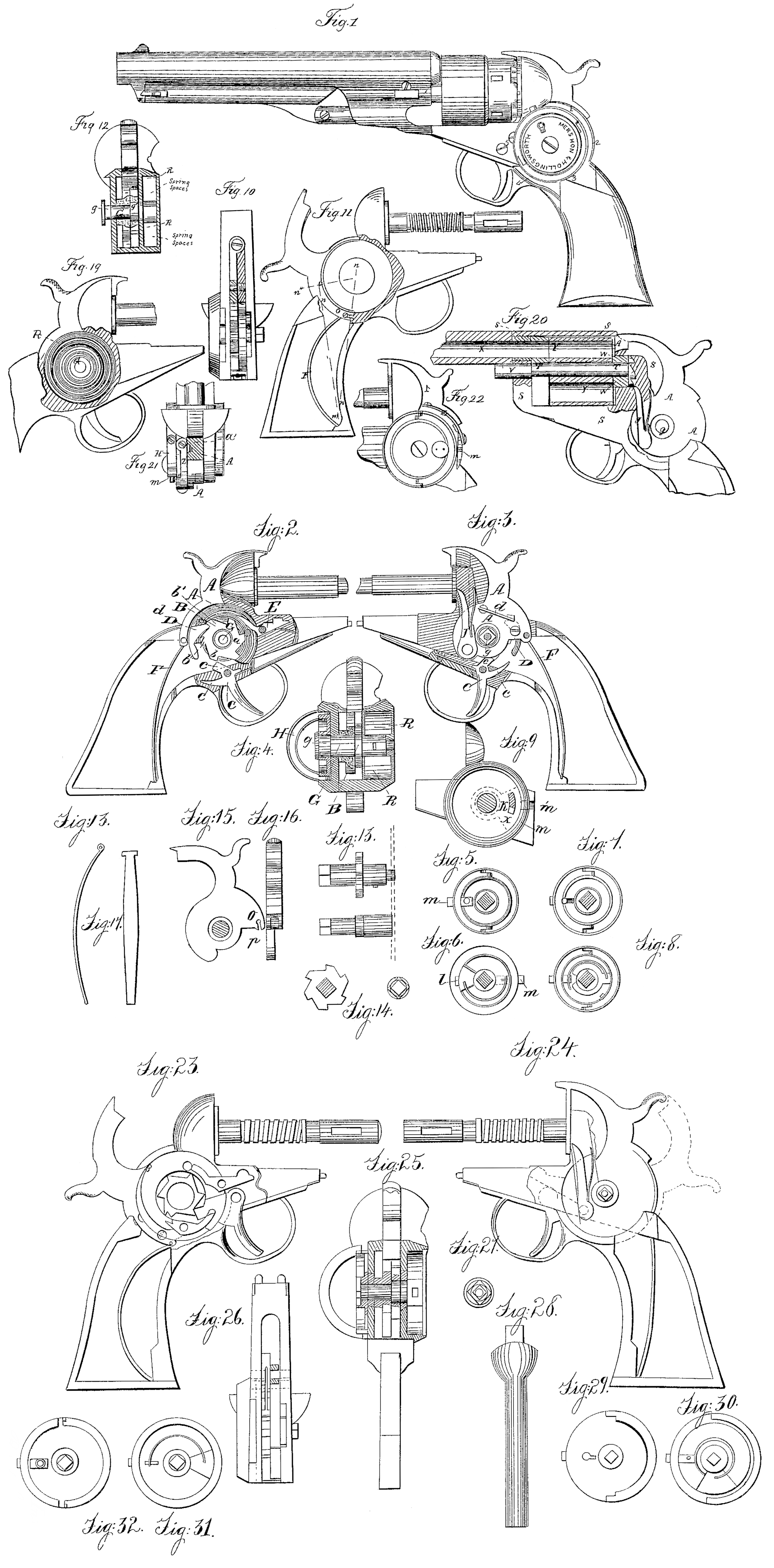
In the drawings, Figure 1 represents the arm complete; Figs. 2 and 3, the right and left sides of the lock-frame of the same having portions of the said frame removed in or der to show the internal parts more fully. Fig. 4 represents a section of the arm in the region of the reservoir spring box and hammer, showing the location and arrangement of the reservoir spring-arbor, the escapement-wheel and the winding-disk. Figs. 5, 6, 7, and 8 represent different views of the winding-disk; and Fig. 9, the cheek or side of the lock-frame, upon which is shown the location of the stop-work for regulating or limiting the number of turns or revolutions to be given in compressing or replenishing the reservoir of power. Fig. 10 represents a view of the lower side of the lock-frame, and the location and distribution of some of the parts comprising the lock. Fig. 11 shows the operation of the hammer-spring, and Fig. 12 another arrangement of the parts,
In describing the drawings like letters in each will be used to denote similar parts.
Let AA, Fig. 2, represent the hammer; B, the escape-wheel; C, the trigger; D, the hammer-dog; E, the chamber-bolt; F, the hammer-spring; G, the arbor, upon which the hammer is movable, and around which a spring is wound that bas sufficient strength to operate the arm— i. e., to cock the hammer, liberate, rotate, and lock the chambered cylinder before each discharge, instead of cocking and rotating the same by land. This coiled spring R, Fig. 19, constitutes the reservoir of power, and is compressed or wound up by means of a winding-disk, H, Fig. 4, that is fitted to the square g, formed on the end of the arbor G, Fig. 4.
The escape-wheel B, Fig. 4, is permanently attached to the arbor G, so that in the act of winding it rotates with said arbor, and in the socket of the hammer AA, Fig. 2, (said hammer remaining stationary,) and for the time becomes a ratchet-wheel, and the hammer-dog D, Fig. 2, its pawl. Now, suppose the reservoir of power to have been compressed, on letting go the winding-disk the reservoir is free to act, and the arbor G and its ratchet B, Fig. 2, instantly rotate, carrying with them the hammer-dog D and the hammer A to the position shown in Fig. 11. At the same time the cam a, Fig. 2, comes in contact with the chamber-bolt E, lifting it and liberating the chambers, which are rotated by means of the rotating-finger J, Fig. 3. This movement brings the tail of the hammer-dog D, Fig. 2, between the points of the fork of the trigger C. at c’ c, Fig. 2, and the back or body of the hammer to rest firmly on the frame of the arm, as shown in Fig. 11. To release the hammer pull the trigger C, Fig. 2. This will bring the point c’ in front of the scape-wheel tooth b, preventing it from rotating. At the same time the point c, pressing upon the tail of the hammer-dog, will lift said dog from the tooth b’ of the scape-wheel B, and the hammer will fall. Then release or let go the trigger. This will liberate the scape-wheel, which will instantly rotate. Its next tooth will meet the hammer-dog D (said dog being held in position by the little spring d, Fig. 3) and carry it and the hammer back to the position it occupied, before pulling the trigger. This operation may be repeated as rapidly as the trigger can be pulled and let go, the cocking of the hammer and rotating the chambers being simultaneous.
As most repeating-arms have but one cylinder, we think it proper to limit the action of the reservoir to one revolution, because, if it did more, it might through forgetfulness become exhausted before a second series of charges could be fired from the chambers. We have therefore made a single revolution of the Winding-disk equivalent to one revolution of the chambered cylinder. To do this we have devised a stop-work, so that said reservoir-spring may be compressed to a certain degree and no more, that it may be exhausted so far and no farther, which further insures the use of the middle turns of the reservoir-spring, and consequently an approximate uniform power.
Fig. 9 represents the cheek-piece removed from Fig. 3. Around the hub, at the center of said cheek and on the inner side, is fitted a friction-collar, K, (in dotted lines,) provided with a fan-shaped extension having a square pin, k, placed in it and reaching through the circular slot in said cheek. This friction-collar moves with sufficient freedom to admit of its being pushed from one side to the other of said slot with a slight pressure.
Fig.6^6 represents the reverse of the winding disk. The square pin l, near the circumference of said figure, corresponds with the pink in the friction-collar K, Fig. 9, and in the act of turning said winding-disk comes in contact with said pin k and moves it forward in the circular slot. By a careful fitting of said pink to the slot we obtain one exact revolution of the winding disk and no more. It is obvious that on the return of said winding-disk exactly the reverse of the motion just described will occur and one complete revolution be obtained. Said disk is further provided with a self-acting spring-bolt, m m, Figs. 5 and 6, which at the completion of each revolution of said disk enters the corresponding notch, m, Fig.9, rendering said disk for the time permanent, and consequently holding the arbor and scape-wheel fixed. Now, if by the hand the hammer be drawn backward, it will carry the dog D, Fig. 2, with it and over the points of the teeth b” of the scape-wheel B, where it will, on removing the hand, stand cocked, the effect being similar to cocking an ordinary arm. Said dog D being brought into the same relation to the trigger C as already described, a simple pull of the trigger will liberate the hammer, while the scape-wheel, being bolted, as already described, will remain fixed, and the arm may be worked at pleasure as a hand-cocking Weapon. Let us suppose now, that with the right hand we lift that portion of the winding-disk that is represented as hinged in Figs. 4,5,6,7,8 to the position shown in Fig. 4. With the left hand take hold of the arm, in the region of the hammer, in such a way as to prevent the hammer from having any motion whatever, draw the spring-bolt m from its corresponding notch with the third finger of the right hand, and turn, by means of the semicircular lever H, Fig. 4, the winding-disk toward us. Let us make an entire revolution, which will bring the spring-bolt m again in the notch, and, although the reservoir is compressed by this movement, still the arm may be used as a hand-cocking weapon. But press firmly upon the spring-bolt pusher m’, and mark what follows. Instantly the scape-wheel rotates, carrying the hammer to a full-cock, liberating, rotating, and locking the chambered cylinder, and the arm is a self-cocking weapon, no other manipulation being required beyond pulling the trigger to discharge it.
It will be observed by the foregoing that the working of the arm can be instantly changed from hand-cocking to self-cocking, and that when the reservoir has exhausted itself the action of the self-cocking mechanism is suspended by the spring-bolt in slipping into its corresponding notch, whereby the disk, arbor, and scape wheel are held, as already described, and the arm becomes again a hand-cocking weapon. Should the ability of the reservoir become accidentally suspended in consequence of the breaking of the coiled springs, or from any cause, the arm remains equal in effectiveness to the best of its kind known, provided the winding-disk be bolted, as already described, being thereby reduced to a hand-cocking arm.
Fig. 12 shows another plan of arranging the internal parts of the lock portions of the arm without removing either of the sides or cheeks of the lock. The figure represents a section similar to that described already in Fig. 4, and the difference in the arrangement and construction of the parts in each, the amount of space occupied, and the distribution of the several pieces upon the arbor G. In this figure said arbor is represented as being furnished with two squares, one,g, is intended to receive the winding-disk, the other, g’, to receive the scape-wheel, both of which are more clearly shown in Figs. 13 and 14.
Figs. 11, 15, 16, 17, and 18 represent respectively the application, the mode of attaching, and operation of the hammer-spring.
Fig. 11 shows the hammer at full-cock and its spring at the greatest compression. The said spring is attached to the hammer either by means of an eye formed in its upper end, and corresponding to a similar part in the hammer, as shown in Figs, 18 and 2 and 3, having a small pin to pass through said eye, forming a pivot or connection for it; or said spring may be constructed in the manner and of the shape of that shown in Fig. 17, having instead of an eye a T-shaped termination at its upper end. The arms of the said T are to be introduced into the slit or opening p at the heel of said hammer, Fig. 15, and from that into the eye O, which becomes a socket for the arms to play in during the action of the hammer, without any liability of slipping from the slit p. This shape makes the spring easier to attach, and allows a freer motion than the mode first described.
Fig. 16 shows the rear of the hammer and the opening in which the neck of the spring plays. When the hammer is at full-cock, as shown in Fig. 11, a line drawn from the center of its axis to the lower end of the hammer-spring will be found to pass very near the eye or socket O. In other words, when the hammer stands at full-cock the power of its spring is exerted in nearly a direct line to the center, and hence almost inactive, having barely sufficient leverage to start the hammer forward at the moment of its release; but as the hammer goes down the effective power of the spring in creases, because the point o, Fig. 11, becomes o’, and the lever whereby the spring propels the hammer is increased from less than one-fourth inch to a length equal to the radius o’ n at least six times, and although the elastic force of the spring is much diminished its effective propelling or striking force is greater than at the start. We believe this is a novel, simple, and useful application of a spring to the hammer of a fire-arm. It enables us to use a light spring, insures greater activity, and continually-increasing propelling force, and is exceedingly simple of construction. In nearly all other arms the action of the hammer-spring is the reverse of this. When we begin to lift the hammer from the nipple we find much less muscular exertion necessary; but as the hammer is elevated the spring becomes stronger, and before reaching the full-cock the power required to overcome it must be more than doubled. As soon therefore as the hammer is released it starts forward with great propelling force, but at the instant of percussion is very much diminished in effective force, and although an exceedingly strong spring is used, the blow of the hammer we believe to be disproportionate; besides, a heavy spring subjected to great compression is much more liable to break than a light one constructed and operating like ours.
Fig. 20 shows a mode of constructing an arm to which the reservoir of power may be applied in which metallic cartridges are used. Let A A A represent the hammer; S S S S S, a section of the frame of the arm into which the barrel is screwed and permanent instead of movable, as show) in Figs. 1, 2, aid 3. Let Y Y represent a section of the chambered cylinder, which is fitted to said frame, having a square hole through its center, to which is fitted the square spindle T T. Said cylinder is intended to revolve with said spindle, the square portion of it performing the office of carrier. The spindle is supported at the front of the frame by passing through a round hole the corresponding portion of the spindle v, fitting the same so as to admit its turning freely in it, and in the rear by entering a square hole or socket in the toothed disk W W W, said disk being movable in said frame. In the act of cocking the hammer the rotating-finger J is brought to operate upon one of the teeth of the disk W W W, turning it in its bearing, together with the cylinder YY and the spindle T T. To remove the cylinder withdraw the spindle TT from the toothed disk W W W and from the frame S S S S S. This construction admits of the frame of the arm being one piece, and prevents the working portions from becoming dirty from powder, smoke, &c., because they are all confined within the lock-frame and in the rear of the chambered cylinder. The reservoir of power is especially applicable to all kinds of repeating or revolving fire-arms in which metallic cartridges or fixed ammunition is used, whether pistols, carbines, rifles, or shot-guns.
Sportsmen greatly prefer an ordinary double-barreled gun to one of the repeating or revolving kind that requires cocking by hand before each discharge, for the reason that the hammers of both barrels may be cocked and ready to discharge as rapidly as two triggers can be pull d, which insures them two shots without removing the piece from the shoulder or disturbing the general line of sight, while with an ordinary repeating-gun they could have but one, because after each discharge the piece must come down from position, be cocked, and releveled before it can be again fired. But an arm that possesses the ability to perform the office of cocking the hammer, liberate, rotate, and lock the chambered cylinder without requiring any other manipulation than the simple one of letting go the trigger after it has been pulled to discharge the arm must be vastly superior to all arms that require the working to be done by the hand.
In arranging the several pieces on the arbor, as herein described, it may be desirable to place the hammer at the outside of the lock and the reservoir of power it the center for the purpose of gaining some space or making a more symmetrical appearance. This arrangement is substantially the same, and does not affect the general principle and operation of the arm, being merely an equivalent.
In loading and capping the chambers when they are not removed from the frame it is necessary to elevate the hammer sufficiently to liberate the chambers so they may be rotated by hand in order to cap and load each in its turn; or this may be effected by a movable hook placed on the outside of the lock-frame, which can be inserted into a corresponding hole cut in the side of the hammer. (See location and arrangement of said hook, designated by letter Z, in Figs. 21 and 22.) The hole in the side of the hammer, which corresponds to said hook Z, is designated by u’ in Fig. 21. This hook is shown in Figs. 21 and 22 in red ink.
Figs. 23 to 32, inclusive, in Plate 3, represent a complete working-drawing of a sectional view of an arm, the arrangement of the lock of which is shown in Figs. 10 and 12, Plate 1, the object being above set forth in the reference to said figures.
Having, as we believe, fully described our invention, what we claim as new therein, and for which we are desirous of obtaining Letters Patent of the United States, is—
1. The application of a reservoir of power to a repeating fire-arm, as described herein, for the purpose of cocking the hammer, and by it liberating, rotating, and locking the chambered cylinder simultaneously for one or more discharges without using the hand to cock the arm, as in the ordinary way.
2. So combining the reservoir of power with the hammer and its independent spring, as herein described, that the action of the reservoir of power can be instantly-suspended and the hammer cocked, chambered cylinder liberated, rotated, and locked by hand, as in ordinary hand-cocking revolving fire-arms.
3. The axis (shaft or spindle) on which is placed the arbor for the coiled spring, the scape-wheel, the hammer, the stop-work, and the winding-disk, as herein described, in combination with the reservoir of power or coiled spring acting as a spindle or bearer for each piece.
4. The combination of the reservoir of power with an arbor, scape-wheel, hammer, hammer-dog, hammer-finger, chamber-lock, chambered cylinder, and trigger, as herein described, so that when the reservoir of power is wound up by pulling the trigger the hammer will be liberated and the arm discharged, and then by simply letting go the trigger the hammer will be instantly cocked, chambered cylinder liberated, rotated, and locked, ready for another discharge.
5. The combination of the reservoir of power with the stop-work, as herein described, for the purpose of limiting the power and action of the reservoir of power.
6. The combination of the reservoir of power with the winding-disk, as herein described, for the purpose of accumulating power by winding up said reservoir of power.
7. The combination of the reservoir of power with the winding-disk and bolt, substantially as described, for the purpose of suspending the action of the reservoir of power, so that the arm can be operated by hand.
8. The combination of the trigger and its two arms or forks with the scape-wheel, and also with the hammer-dog, as herein described, so that when the trigger is pulled one of the arms will liberate the hammer-dog and hammer and permit the arm to be discharged, and at the same time its other arm will be entering into a scape-wheel tooth or notch, thus holding at rest the scape-wheel and reservoir of power, the arm or fork which has been holding the scape-wheel and reservoir of power at rest being withdrawn by releasing or letting go the trigger, the reservoir of power and scape-wheel will become free to act, and will by means of the hammer-dog rotate and cock the hammer, and by it liberate, turn, and lock the chambered cylinder in its place, ready for another discharge.
9. The application of the self-cocking mechanism herein described to all chambered cylinders in which metallic cartridges are used.
RALPH. S. MERSHON,
JEHU HOLLINGSWORTH.
Witnesses:
Eug. H. Munday,
E. G. Putnam.