
US 39850
UNITED STATES PATENT OFFICE.
H. D. WARD, OF PITTSFIELD, MASSACHUSETTS.
IMPROVEMENT IN DOUBLE-BARRELED REVOLVING FIRE-ARMS.
Specification forming part of Letters Patent No. 39,850, dated September 8, 1863.
To all whom it may concern:
Be it known that I, H. D. Ward, of Pittsfield, in the county of Berkshire and State of Massachusetts, have invented certain new and useful Improvements in Revolving Fire-Arms; and I do hereby declare that the following is a full, clear, and exact description of the same, reference being had to the accompanying drawings, forming part of this specification.
This invention consists in so applying two barrels, in combination with one cylinder having a single circle of chambers, as to provide either for the discharging of two of the said chambers, one through each barrel, without rotating the cylinder between the discharges, or for the discharge of the several chambers successively through one of the said barrels, like the chambers of an ordinary revolver, as may be desired.
It also consists in certain means of combining two hammers, a trigger, and a device for rotating the cylinder in a fire-arm having two barrels and a single cylinder, that one of the hammers may be cocked separately for firing from one chamber, or both may be cocked together for firing from two chambers, and that when one hammer only is cocked the cylinder may be caused to rotate only a distance corresponding with the distance between the center of one chamber and the center of the next one, but that when the two hammers are cocked together the cylinder may be caused by the cocking movement to rotate twice the afore said distance.
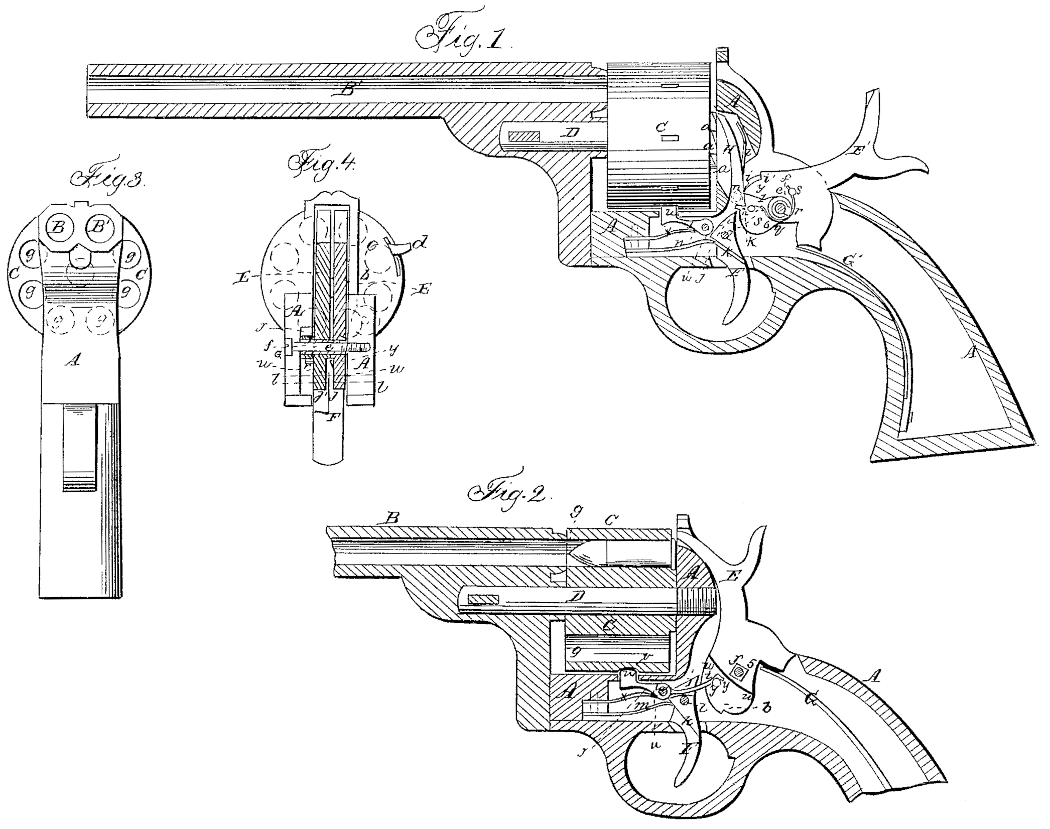
Figure 1 in the accompanying drawings exhibits a vertical longitudinal section through the frame and the left-hand barrel, and a side view of the cylinder of a pistol constructed according to my invention. Fig. 2 is a vertical longitudinal section of the frame, the cylinder, and the right-hand barrel of the same. Fig. 3 is a front view of the same. Fig. 4 is a transverse vertical section of the same in the plane indicated by the line x x, Figs. 1 and 2.
Similar letters of reference indicate corresponding parts in the several figures.
A is the frame. B B are the two barrels. C is the cylinder, and D is the axis-pin.
The two barrels may be either made of one piece of metal or made separately and secured together in any suitable manner; and the frame, the axis-pin, and the cylinder are constructed and combined with each other and with the barrels in substantially the same manner as in single-barreled revolving fire-arms.
The cylinders should have an even number of chambers, g g, at equal distances apart and at equal distances from its axis, such number being as large as practicable without making the cylinder inconveniently large. The bores of the two barrels or double barrel are at distances from the axis-pin corresponding with the distances of the chambers therefrom, and are at a distance apart corresponding with the distances between the chambers, so that any two immediately adjacent chambers may be brought opposite the said bores, one opposite to each, to permit them to be discharged, one through each barrel, without rotating the cylinder between the discharges.
The chambers of the cylinder may be constructed in various ways, according to the kind of ammunition used. In the example represented they are constructed to be loaded from the rear with fixed ammunition. The cylinder is made like that of single-barreled revolving fire-arms, with a series of ratchet-teeth, a a, corresponding in number with the chambers upon its rear end. To obviate the necessity of taking out the cylinder for loading, a portion, b, of the recoil-shield is made capable of opening sidewise upon a pivot, c, Fig. 4, and secured, when closed, by a catch, d.
E E’ are the two hammers, arranged side by side in such manner that one may strike upon and ignite the priming of the ammunition in one, and the other strike upon and ignite the priming of that in the other, of any two of the chambers of the cylinders which are opposite the two bores of the barrel. These hammers are constructed substantially like those of other fire-arms, and both held in place by the stationary pin e, which is inserted transversely through the frame, such pin corresponding with that upon which the hammer works in other fire-arms; but instead of being fitted directly to the said pin the hammers are both fitted to a sleeve, f, which is fitted to turn on the said pin, the right-hand hammer, E, being fitted to a square portion, 5, of the exterior of the said sleeve, and the left-hand hammer, E’, fitted to a round portion, 6, of the exterior of said sleeve, so that the latter one can turn on the sleeve, and the former only can only turn with the sleeve upon the pin e. Each hammer has in its tumbler, which is made in the same piece with it, a full-cock notch and a half-cock notch. The full-cock notches h h’ are made in corresponding positions. The half-cock notch i of the left-hand hammer is made higher up on the tumbler than the corresponding notch i of the right-hand hammer, and has also a fuller projection above it. The hammers are operated by separate mainsprings G G’; but these may be formed of the same piece of steel slit or forked in a suitable manner.
F is a trigger, arranged to work upon a pin, l, in the usual manner. This trigger has the sear j, belonging to the right-hand hammer, E, made in the same piece with it. The sear j’, belonging to the left-hand hammer, is made of a separate piece and arranged to work upon the trigger-pin l, and so fitted to a shoulder, k, on the trigger as to allow the trigger and sear i to have a suitable amount of movement independent of it, so that when both hammers have been cocked the right-hand sear, j, may be drawn from the full-cock notch i of its respect ive hammer E by the pulling back of the trigger before the left-hand sear, j’, is drawn from the corresponding notch of its respective hammer E’. The trigger has applied to it a spring, m, which tends to press the sear j toward the tumbler of the hammer E, and the sear j’ has applied to it a spring, n, to press it toward the tumbler of the hammer E’.
H, Fig. 1, is the dog, which operates upon the ratchet-teeth a a to produce the rotary, movement of the cylinder. This dog is attached by a pin-joint, n, to an arm, I, which is fitted loosely to the round portion 6 of the sleeve if on the left hand or outer side of the left-hand hammer, E’, and the said sleeve has a projection, p, so arranged as to be capable of acting upon a projection, q, on the said arm, for the purpose of moving the said arm, with the said sleeve, to effect the necessary movement of the dog H to produce the rotation of the cylinder, but of permitting the hammer E to move independently of the said arm far enough to allow the said hammer to be half-cocked before the rotating movement of the cylinder commences. The said arm I has applied to it a spring, r, which bears against a pin, s, secured in the left-hand hammer, E, for the purpose of pressing down the said arm, and so drawing back the dog from the ratchet as the hammer E’ descends or moves forward in firing. This arm is supported upon a pin or projection, t, on the left or outer side of the left-hand hammer at all times; but while the right-hand hammer is being cocked independently of the left-hand one the dog H is pressed forward against the ratchet-teeth by a spring, z.
J is the stop-lever, for stopping and locking the cylinder with its chambers in line with the bores of the barrels, arranged to work on a fixed fulcrum-pin, u, in the lower part of the frame A. This lever has at its front end a tooth, u’, to enter either of a series of notches, v v, in the periphery of the cylinder. The portion of the said lever in rear of its fulcrum-pin is made thin enough in a lateral direction to enable it to work between the tumblers of the two hammers in recesses w, formed in the inner faces of the hammers. The said lever has applied under its front portion a spring, x, to press its tooth upward against the periphery of and into the notches in the cylinder. y is a pin, secured in and projecting from the tumbler of the hammer E, to act upon the rear portion of the stop-lever J, to withdraw the tooth u from the notches of the cylinder by the act of drawing back the hammer E to cock it. This pin is so arranged that just before the hammer arrives at full-cock it passes the end of the lever and allows the spring x to press the tooth of the dog up against the periphery of the cylinder, and hold it there in readiness to slip into one of the notches v v as the hammer arrives at full-cock and the cylinder completes its rotating movement. The end of the said pin is so beveled in a downward direction that as the hammer E falls the said pin springs aside the back portion of the lever, and so passes it without unlocking the cylinder.
The chambers of the cylinder having been loaded, the operations of cocking the hammers and rotating the cylinder are as follows: If it be desired to fire but once, the right-hand hammer, E’, alone is cocked, and in drawing it back to cock it it turns the sleeve f, by reason of its being fitted to the square 5, as hereinbefore described, without moving the left-hand one, and the projection p on the sleeve acts upon the projection g of the arm I to raise the latter, and thereby move the dog upward against one of the ratchet-teeth a a and produce the necessary movement of the cylinder, such rotary movement, owing to the lost motion provided for between the projections p and q, being only to the extent of the distance between the center of the next one. On pulling the trigger the said hammer E explodes the charge in the chamber which is opposite to the right hand barrel. This operation with one hammer and barrel can be repeated until all the chambers have been discharged. When it is desired to discharge two chambers without recocking between the discharges both hammers are drawn back together by the movement of the left-hand hammer, E’, the pin s is caused to raise the arm I from the commencement of the said movement, and the dog His thereby caused to turn the cylinder a distance equal to twice the distance from the center of one chamber to the center of the next one. By pulling the trigger the right-hand hammer, E, is first released, as the sear j’, by reason of its being detached from the trigger, does not so soon escape from the cock-notch in the tumbler of the hammer, and by the continued pull after the escape of the right-hand hammer the left-hand hammer falls, and in this way two chambers may be discharged, one through each barrel, either in such rapid succession that the discharge seems to be instantaneous or with the intermission of any desirable interval between the discharges, in the first case the trigger being pulled directly back the whole distance at once, and in the latter case being pulled back until the first hammer is felt to escape, and then allowed to rest for a time before pulling it back the remainder of the distance. By recocking the two hammers at once the cylinder is moved far enough to carry away from the barrels the two discharged chambers and present two charged ones.
What I claim as my invention, and desire to secure by Letters Patent, is—
1. So applying two barrels, in combination with one rotating cylinder having a single circle of chambers, as to provide either for the discharge of two of the said chambers, one through each barrel, without rotating the cylinder between the discharges, or for the discharge of the several chambers successively through one of the said barrels, substantially as herein described.
2, Combining the two hammers with each other and with the dog h for rotating the cylinder by means of the sleeve for its equivalent, having a projection, p, the arm I, having a projection, q, the spring r, and the pin or projection s, the whole arranged to operate substantially as and for the purpose herein specified.
H. D. WARD.
Witnesses:
Geo. N. Dutton,
H. M. Peirson.