
US 39771
UNITED STATES PATENT OFFICE.
CHARLES W. HARRIS, OF PITTSBURG, PENNSYLVANIA, ASSIGNOR TO JAMES MASLIN COOPER, OF SAME PLACE.
IMPROVEMENT IN REVOLVING FIRE-ARMS.
Specification forming part of Letters Patent No. 39,771, dated September 1, 1863.
To all whom it may concern:
Be it, known that I, CHARLES W. HARRIS, of the city of Pittsburg, in the county of Allegheny and State of Pennsylvania, have invented a new and useful improvement in Revolving-Breech Fire-Arms; and I do hereby declare the following to be a full, clear, and exact description thereof, reference being had to the annexed drawings, forming part of this specification, in which–
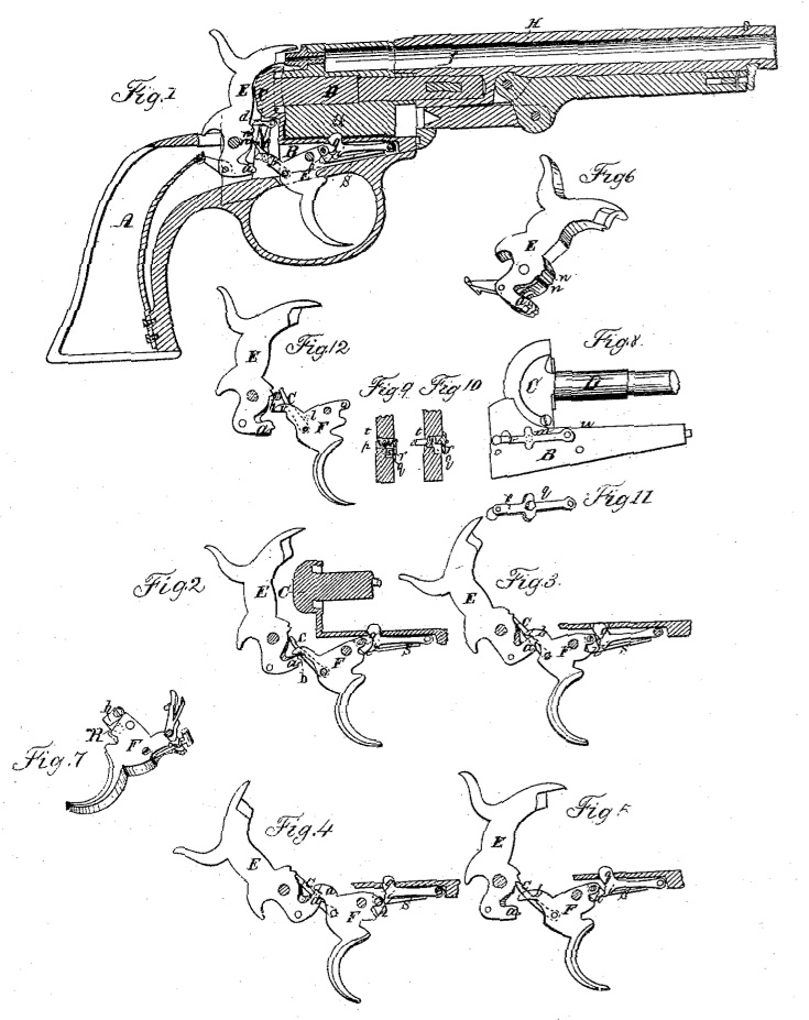
Figure 1 is a sectional side view of a revolving breech fire-arm. Fig. 2 represents the parts of the lock of the pistol with the hammer drawn partially back, so as to engage the heel of the trigger, Fig. 3 represents the relative position of the parts of the lock before the hammer reacies tie point of full-cock at the moment when the locking-bolt is withdrawn. Fig. 4 shows the relative position of the parts of the lock when the laminer is at full-cock. Fig. 5 represents the parts of the lock when the trigger has recovered itself after firing, being the same as in Fig. 1. Fig.6 is a perspective representation of the hammer. Fig. 7 is a perspective representation of the trigger with the hand or driver attached, showing the vibrating pawl for operating the locking-bolt. Fig. 8 is a side view of the lock-fraine and recoil-shield, showing slide for operating the cut off. Figs. 9 and 10 are cross-sections through one side of the lock-frame, showing the cut-off and the manner of operating it. Fig. 11 is a perspective view of the slide for operating the cut-off, Fig. 12 is a representation of the hammer and trigger, showing the effect of the cut off.
In the several figures like letters of reference denote similar parts.
The drawings accompanying this specification represent a double-action revolving-breech pistol–that is, the pistol may be cocked and fired either by raising the hammer by hand or by pulling the trigger; and my invention consists in certain improvements in the lock, affecting the operation of the hammer, trigger, and locking-bolt, which holds the revolving cylinder in place.
In the drawings, A is the stock of the pistol; B, the lock-frame, to which the several parts of the lock are attached. C is the recoil shield, from which projects the arbor or base-pin D, on which the revolving chambered breech resolves, E is the hammer; F, the trigger, and H the barrel.
In Fig. 1 the parts are shown in their position at rest-that is, when the hammer is down and the trigger not drawn back.
The lock operates either by harner or trigger–that is to say, if the hammer E be raised by land, the toe a of the hammer, coming in contact with the heel b of the trigger, raises it, and thereby draws back the trigger, cocking the pistol, rotating and locking the breech, and setting the trigger ready for firing. If, on the other hand, the trigger be pulled back with. out first cocking the hammer, the same results are obtained. The trigger raises the hammer by means of the cock-pawl c, and when at half-cock the half-cock pawl d enters the notch n’, and when at full-cock the hammer is held in place by the pawl c, as seen in Fig. 4. When the trigger is rising, the finger which is pivoted to the trigger near to its rear end engages a notch in the neck of the revolving breech and causes it to rotate far enough to bring one of the charge-chambers in range with the point of the banner and of the barrel H. The locking-bolt g is pressed upward by its spring s, its head passing through a hole in the lock-frame B, and pressing against the periphery of the revolving breech and entering a notch therein just when one of its chambers comes in range with the bore of the barrel, this locking it in position.
Just before the revolving breech begins to revolve by the action of the finger e, operated by trigger F, it is necessary to release the positive locking-bolt from the notch in the revolving breech, which is effected by means of a vibrating pawl, h, pivoted to the toe of the trigger, as seen in Fig. 7. A spiral spring, k, (shown by dotted lines in Fig. 7,) serves to keep the vibrating pawl, pressed forward and allows it to be depressed by the tail i of the locking-bolt, when the trigger recovers its position after firing and when the hammer is at full-cock, as seen in Fig. 4. This vibrating pawl is my improvement on the device for operating the positive locking-bolt invented by J. Maslin Cooper, as it secures more certainty of action. It will be seen by examining Figs.1 to 5, that when the trigger is first drawn back it begins to depress the locking-bolt, and before the hammer arrives at full-cock, as in Fig. 3, the head of the locking-bolt is drawn completely down, thus leaving the revolving breech cylinder free to rotate on its axis; but just before the hammer arrives at the point of full-cock as at Fig. 4, the vibrating pawl slips off the tail i of the locking-bolt g and allows it to spring back against the revolving breech, thus again locking it in position. When the piece is fired and the trigger returns to its first position the vibrating pawl is depressed by the tail i of the locking-bolt g and recovers its place over the tail of the locking-bolt, as in Fig. 5, ready to operate it, as just described.
Another improvement consists in so constructing the toe a of the hammer as that when in place in the lock-frame, and the parts are at rest, as in Fig. 1, the toe of the hammer will not touch the tail of the trigger. The effect of this arrangement is that the hammer may be raised slightly by hand without affecting the trigger or operating any of the other parts of the lock, as may be seen by Fig. 2, where the trigger and all the parts of the lock operated thereby remain as at first. The advantage of this is that in case a piece of cap or other substance gets into the groove for the hammer in the lock-frame, so that the hammer, cannot fall completely down after the trigger is pulled, the trigger is not prevented thereby from recovering its position, but will return to its place, with the pawl c, under the lower notch, n, in the hammer, as seen in Fig. 2, so that the hammer may be raised by drawing back the trigger and the piece of cap removed. This depression of the toe of the hammer is especially important on those fire-arms which are exclusively trigger – operating, because by the old arrangement the trigger cannot get into position to act on the hammer to raise it if the hammer does not fall completely down when the trigger is pulled.
Another improvement is a peculiar device applicable to double-action firearms, designed to render them solely hammer-operating when desired.
Many persons prefer to have their fire-arms to operate so as to be cocked only by pulling back the trigger by hand, and it is convenient to have an arrangement by which this change may be readily effected. To accomplish this I bore a small round hole, m, (see Fig. 8,) in the lock-frame B, into which I insert a small bolt, p, surrounded by a spiral spring, t, which is kept in place by the head of the bolt on one side and by an offset in the hole on at the other, as seen in Figs, 9 and 10. By this spiral spring t the bolt p is drawn back into the wall of the lock-frame B, as in Fig. 10; but it may be pressed inward, so as to protrude into the cavity of the lock-frame, by means of a beveled projection, q, (see Fig. 11,) on the under side of the lever r, which lever is pivoted at u to the lock-frame, so that by raising or lowering the free end of the lever r the spring-bolt p is protruded into the cavity of the lock-frame or allowed to recede. The position of the bolt p in the lock-frame relatively to the hammer and trigger is shown in Fig. 12, being such that when the trigger is drawn-back the bolt may be pushed forward; but when the trigger is at rest it cannot be forced into the cavity of the lock-frame. This is so arranged in order that the change in the fire-arm of depriving it of its trigger-operating feature may not be made accidentally, but must be done, if at all, by design, and yet the reverse operation of restoring the trigger-operating action may be effected in any position of the trigger by lowering the lever r, and thus withdrawing the bolt p. The effect.of the introduction of the bolt p into the cavity of the lock-frame is seen in Fig. 12. The bolt slips in between the cock-pawl e (which is attached to the trigger and raises the hammer) and the hammer, and prevents the cock-pawl or hand e from entering the full-cock notch n in the face of the hammer, and thus effectually prevents the cocking of the pistol by the pulling of the trigger.
Having thus described my improvement in revolving-breech fire-arms, I do not claim as my invention the use of a positive locking bolt in fire-arms, susceptible of operation by the trigger, by which I mean a device for locking the rotating charge-cylinder, so constructed and arranged as constantly to press up against the face of the charge-cylinder excepting when necessarily withdrawn to allow of its rotation, as I believe that to be the invention of J. Maslin Cooper; but
What I do claim as my invention, as an improvement to the positive locking-bolt, is–
1. The use, in combination therewith in revolving fire-arms, susceptible of operation by the trigger, of a vibrating pawl at the forward end of the trigger for the purpose of operating the locking bolt, so that as the trigger is released after the pistol bas been fired and is regaining its position for repeated action the extremity of the vibrating pawl will recede, passing under the locking-bolt, and thereby engaging it again, so that when the trigger is pulled in firing the pistol it will immediately draw down the head of the locking bolt out of its recess in the charge-cylinder, and so hold it until the hammer is at half-cock, when the vibrating pawl releases the bolt and allows it to react against the face of the charge cylinder, ready to drop into the notch in the cylinder as soon as the cylinder is sufficiently turned, substantially as hereinbefore described.
2. The use of a cut-off consisting of a spring bolt or other suitable device which may be operated from outside of the lock-frame for holding the cock-pawl of the trigger off from the toe of the hammer, so that it cannot engage the cock-notch in the hammer, and thus at will preventing the hammer being raised by the trigger whenever it is desired to have the pistol operate exclusively as a hammer-cocking arm
3. Lowering the toe of the hammer so that when in position in the lock-frame before the piece is fired the toe of the hammer will not be in contact with the rear end of the trigger, and thereby giving a slight play to the hammer and permitting of its being raised slightly without drawing back the trigger, in order that the trigger may regain its proper position after firing, even though the hammer should have been prevented from falling completely by a piece of exploded cap or other obstruction, substantially as hereinbefore described.
In testimony whereof, I, the said CHARLES W. HARRIS, have hereunto set my hand.
CHAS. W. HARRIS.
Witnesses:
GEORGE TAYLOR,
W. BAKEWELL