
US 39642
UNITED STATES PATENT OFFICE.
M. F. GERAGHTY, OF JERSEY CITY, NEW JERSEY.
IMPROVEMENT IN REVOLVING FIRE-ARMS.
Specification forming part of Letters Patent No. 39,642, dated August 25, 1863.
To all whom it may concern:
Be it known that I, Michael F. Geraghty, of Jersey City, in the county of Hudson and State of New Jersey, have invented a new and useful Improvement in Revolving Fire-Arms; and I do hereby declare that the following is a full, clear, and exact description of the same, reference being had to the accompanying drawings, forming a part of this specification, in which—
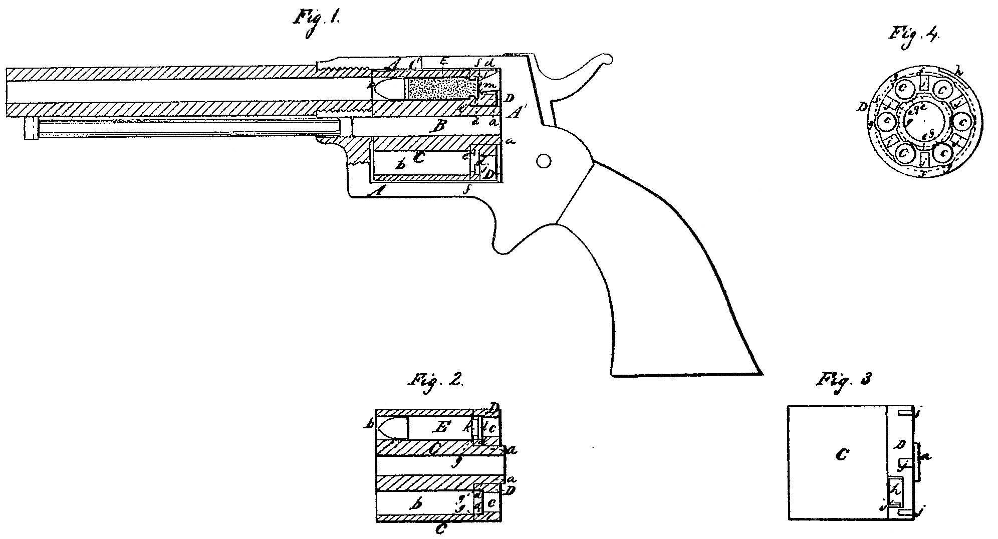
Figure 1 is a side view of a pistol with my improvement, the barrel and cylinder being represented in section. Fig. 2 is an axial section of the cylinder. Fig. 3 is a side view of the same. Fig. 4 is a front view of the rear portion of the cylinder.
Similar letters of reference indicate corresponding parts in the several figures.
This invention relates to revolving fire-arms for the use of metallic cartridges inserted in the chambers from in front of the cylinder. Its object is to provide for securing such cartridges in the chambers in such manner that they can neither drop out in front nor move forward therein, and thereby interfere with the revolution of the cylinder.
To enable others skilled in the art to make and use my invention, I will proceed to describe its construction and operation.
A A’ is the frame of the arm, of ordinary construction.
B is the cylinder axis-pin, inserted and secured in the frame in any convenient or suit-able manner.
The cylinder represented is composed of two pieces, C and D, of which C may be spoken of as the body and D the locking-ring. The body C is bored to turn freely on the axis-pin B, and made with a hub, a, upon which the locking-ring is fitted to turn freely, and its entire length, including the hub, is just equal to that of the opening in the frame, that it may rotate freely between the barrel and the recoil-shield A’ without any longitudinal movement. Its front end, which fits against the rear end of the barrel, is flat, and so is the end of the chambered portion outside of the hub. The last mentioned portion is of a length somewhat less than that of the whole length of the cartridges, including the bullets, and the chambers b b are bored right through it, that the cartridge may enter some distance into a cavity, d d, in the front of the locking-ring. The locking-ring is of a depth in all axial direction about or nearly equal to the length of the hub a, and the whole length of the cylinder from one-sixth to a quarter of an inch longer than the whole length of the cartridges, including the bullets. It has drilled through it a circular series of holes, c c, ! corresponding in number and position with the chambers b b in the body C, but smaller than the chambers, and has turned in its front side, opposite the said holes, the annular cavity d d, the width of the back part of which is equal to or not less than the diameter of the chambers b b, and the front part of which is narrower, forming narrow flanges e f on its inner and outer circumferences. The depth of the recess is such that it may receive a sufficient portion of the length of the cartridge protruded through the rears of the chambers to allow the points of the bullets to come within the mouths of the chambers. The flanges e fare cut away opposite to and concentric with each hole c, as shown at g g in Fig. 4, to form openings corresponding in width and position with the chambers b b. Midway between the holes c c there are cut through the back of the ring into the annular cavity d d holes j j for the entrance of the nose m of the hammer, to strike the rear ends of the cartridge-shells and ignite the fulminating priming which is contained therein. The diameter of the exterior periphery of the ring D corresponds with that of the body C of the cylinder, and there is cut in the front part of it a recess, h, Figs. 3 and 4, for the reception of a projection, i, Fig. 3, on the back of the body C, the width of the said recess and projection being such as to permit the ring to turn on the hub a only just far enough to present either the holes cc or those j j opposite to the chambers b b.
The shells E E of the cartridges are made cylindrical or slightly tapering from the front toward the rear, and with grooves or circumferential recesses k at such distance from their front ends that while the points of the bullets are within the chambers b b the said grooves may be received between the flanges e f, the width of the said grooves being equal to the thickness of the said flanges, and the depth of the said grooves being not less than the depth of the said flanges. The portions of the shells in rear of the said grooves are only just long enough for the reception of the fulminating priming, forming thin hollow flanges l in rear of the said grooves.
To load the cylinder the locking-ring D is turned on the hub a to such a position as to bring the holes c c and the openings g g in its flanges e f opposite to the chambers b b, as shown in Fig. 2, and the cartridges are then inserted into the chambers from in front of the cylinder and pushed back through the openings g g in the flanges e f of the rings into the recess d, the whole cylinder being turned as often as is necessary to present the mouths of all the chambers in position for the reception of the cartridges, and the loading being thus effected without removing the cylinder from or opening the frame. When the chambers have been all loaded the ring D is turned on the hub as far as permitted by the projection i— viz., far enough to bring the hammer-openings j j opposite to the cartridges, as shown in Fig. 1; and the flanges e and f, being then received within the grooves k of the cartridge-shells, effectually prevent the slipping forward of the cartridges, and thereby not only prevent them from dropping out of the chambers when the arm is held with the muzzle downward, but prevent them from coming in contact with the frame and interfering with the revolution of the cylinder. To reload after the cartridges in all the chambers have been fired, the locking ring is turned to bring the holes c c opposite the chambers, and a rod, which is kept under the barrel, is inserted from the rear of the cylinder through all (of the said holes in succession to push out the discharged shells E E through the front end of the cylinder, after which the new cartridges are inserted and secured in the same way as before described.
The ratchet-teeth, which are acted upon to produce the revolution of the cylinder in the same way as the teeth upon a cylinder of ordinary construction, are formed upon the rear end of the hub a a.
Instead of making the cylinder of two parts only, it may be made of three— viz., a body like C, a ring secured firmly to the rear end of the body, with holes in it for the reception of the rear ends of the cartridges, and a locking-ring of a thickness only equal to the flanges e f, fitted to turn between the body C and the first-mentioned ring, said locking-ring having its interior cut away at intervals, as shown at g g, in the outer flange, f, of the locking-ring D, and the intervening portions serving, like the flange f, to enter the grooves k in the cartridge-shells and lock the cartridges in the cylinder.
What I claim as my invention, and desire to by Letters Patent, is—
The employment of the locking-ring D, constructed, arranged, combined, and operating in conjunction with the rear portion of the cylinder C and the cartridge-cases E, as herein shown and described.
M. F. GERAGHTY
Witnesses:
Daniel Robertson,
M. S. Partrid E.