
US 178133
UNITED STATES PATENT OFFICE.
SULLIVAN FOREHAND, OF WORCESTER, MASSACHUSETTS, ASSIGNOR TO HIMSELF AND HENRY C. WADSWORTH, OF SAME PLACE.
IMPROVEMENT IN REVOLVERS.
Specification forming part of Letters Patent No. 178,133, dated May 30, 1876; application filed April 10, 1876.
To all whom it may concern:
Be it known that I, SULLIVAN FOREHAND, of the city and county of Worcester and Commonwealth of Massachusetts, have invented certain new and useful Improvements in Revolving Fire-Arms; and I do hereby declare that the following is a full, clear, and exact description of the same, reference being had to the accompanying drawings, forming a part of this specification, and in which–
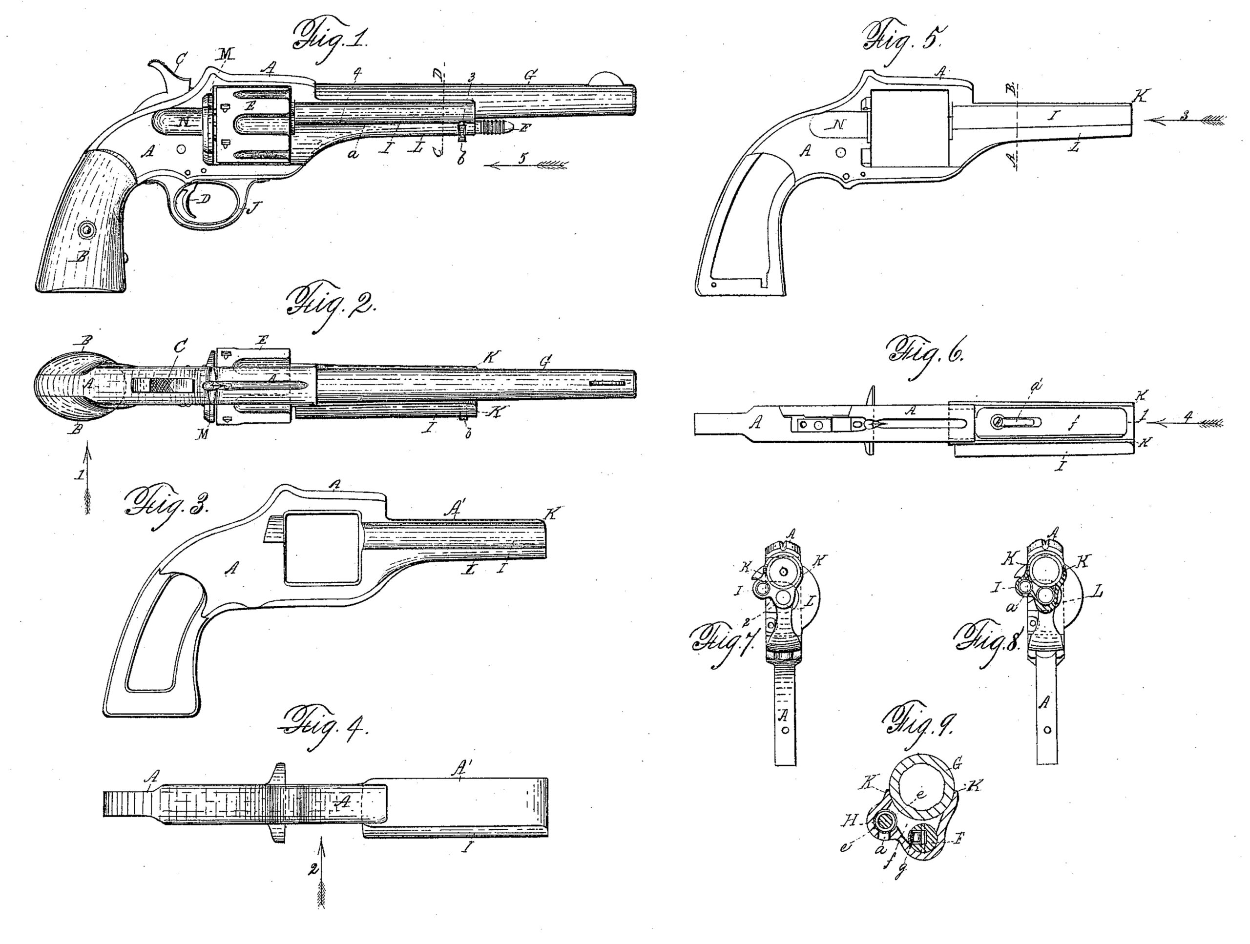
Figure 1 represents a side view of a revolving fire-arm embracing my said invention, looking in the direction of arrow 1, Fig. 2. Fig. 2 represents a top or plan view of the arm shown in Fig. 1. Fig. 3 represents a side view looking in the direction of arrow 2, Fig. 4, from which the frame which supports the stock, lock, trigger-guard, revolving chamber, barrel, center pin, and cartridge-ejector is made, as will be hereafter explained. Fig. 4 represents a top or plan view of the forging shown in Fig. 3. Fig. 5 represents a side view of the forging shown in Fig. 3, after the same has been finished preparatory to receiving the other parts of the arm. Fig. 6 represents a top or plan view of Fig. 5. Fig. 7 represents an end view looking in the direction of arrow 4, Fig. 6. Fig. 8 represents a section on line AB, Fig. 5, looking in the direction of arrow 3, Fig. 5; and Fig. 9 represents a section on line C D, Fig. 1, the rear under part of the arm not being shown.
To enable those skilled in the art to which my invention belongs to make and use the same I will proceed to describe it more in detail.
As revolving fire-arms having a slotted ejector-case arranged along one side of the barrel, for supporting the long ejector-rod and its encircling spring, have heretofore been made, the slotted ejector-case, which necessarily had to have a long narrow slot for the stem or shank of the thumb and finger piece to work back and forth in, have been made separate, both from the frame which supported the chambered cylinder, and also separate from the projecting part of said frame, which supported the barrel, and it was necessary to fasten said slotted ejector-case at one end to the barrel, and at the other end to the main frame; but this form of construction has been found quite defective and objectionable–first, on account of the expense; and, second, for the reason that the barrel, in such cases, was really unsupported upon one side; besides it had to support the slotted ejector case instead of receiving any substantial sup port therefrom, and this has been a very serious objection which military authorities have urged against the use of such form of arm, although highly approving of a slotted ejector-case for supporting the ejector-rod, having a projecting thumb and finger piece for operating the same.
In practice, on the frontier and elsewhere, where such arm has been subjected to severe usage, it has been found that there were great liabilities of the barrel and ejector-case being sprung out of line with the chambered cylinder, in consequence of the end of the barrel being struck so as to force it toward the slotted ejector-case. Besides, the fastenings to the slotted ejector-case were constantly liable to become loosened or displaced, and the principle object of my present invention is to obviate by a substantial and practical improvement on this form of arm the objections heretofore urged against it, as above stated. In the drawings, the part marked A represents the main metallic frame, which is made from a single forging, as shown in Figs. 3 and 4, and which forging is afterward milled and worked into the form shown in Figs. 5, 6, 7, 8, and 9, when it is ready to receive the wooden parts B B of the stock, the lock, the hammer C, and trigger D, all of which are shown in Fig. 1, the revolving chamber E, center-pin F, barrel G, cartridge-ejector H, which works in the case I, and trigger-guard J.
It will be seen that the forwardly-projecting parts K K of the main frame A, in which the chamber E revolves, and which supports the barrel G, and the forwardly-projecting cases I and L, which receive and support the cartridge-shell ejector and center-pin, are made from the same piece of metal, and consequently neither of said parts can be sprung out of its relative position as respects the other parts of the arm, thus insuring great strength and durability and accuracy of operation, while at the same time reducing the cost of construction.
The case L, which receives the center-pin F, upon which the chamber E revolves, affords a strong and rigid support for the lips or parts K K, which support the barrel G, as fully indicated in Figs. 7, 8, and 9, while the slotted ejector-case I, being formed from the same piece of metal as the parts L and K K, affords additional strength to said parts.
It will be understood that the under side of the ejector-case has a slot, a, in which the stem of the thumb and finger piece b, attached to the shell-ejector rod, works back and forth during the operation of ejecting the shells, being forced out into the position shown in Fig. 1, when not in use, by a spiral spring, e, arranged upon the ejector-rod between the stem of thumb-piece b and a shoulder upon the inner surface of case I, near the front end of the revolving chamber E.
The projecting part A’ of the part A is forged solid, and thereafter cut, bored, and milled out for the reception of barrel G, center-pin F, and shell-ejector rod H, the extreme end of the projecting part A’ presenting the form, after it has been finished, shown in Fig. 7, the metal not being cut away between the hole for the center-pin and the case for the ejector-rod. Neither is the metal cut quite through above the hole for the center pin. Consequently, by simply inserting a screw in the end of the slotted case I a very linear and finished appearance is given to the projecting part A’, and it is of sufficient size to look well and be handled with convenience, while the interior part from the rear of the barrel to the point 1, is cut away below the barrel, as shown at f Fig. 9, thereby insuring lightness Without injuriously weakening the strength of the parts I, K K, and L, which are formed from the projecting part A’ of the frame A. In the bottom of the recessed part A’ is secured, in a recess, a flat spring, a’, arranged so as to press up against the center pin F, and by which arrangement the center pin is prevented from moving out, or from slipping back after it has been drawn out to remove the chambered cylinder E. To hold the center-pin in place, as shown in Fig. 1, it is grooved out on one side, and a movable portion, g, is pivoted therein, having on its outer surface a projection, which is forced out inside of flange 2 as soon as the center-pin is pushed into position, as shown in Fig. 1.
The ejector-case I, necessarily weakened and left without a support by the slot cut or formed from the point 3 to near the point 4, and as the case occupies a position above the axis of motion of the revolving chambered cylinder E, it is necessary, as before explained, that it should have a rigid and permanent connection, if possible, with its projecting parts of the frame A, and by my invention this result is accomplished, while, at the same time, the shell-ejector rod H can be and is supported up very close to the barrel G, and that, too, without liability of the end of the ejector-rod striking against the inner edges of the barrels or chambers in the cylinder E when it is forced back to eject the shells.
By combining the slotted ejector-case I with the parts A, L, and K, substantially as above described, whereby the slotted ejector-case has an unbroken union at both front and rear, the arm combines great strength with lightness and durability, while at the same time reducing the cost of construction thereof.
It will be understood that when the shells are to be ejected from the chambered cylinder E the spring-section M is turned back to permit of the shells being forced out in real of the cylinder, a recess, N, being formed in the side of frame A, to permit of the passage of the shells and of the end of the ejector-rod as it moves back close up to the surface of the chambers nearest to the center of the cylinder E. It will thus be seen that the shell-ejector rod, its case, and its thumb-piece are all brought so close to the barrel as not to give the arm a heavy and unsightly appearance, while at the same time the construction and combination are such as to obviate any danger of a deflection, loosening, or derangement of the slotted ejector-rod case under the severest usage.
Having described my improvements in revolving fire-arms, what I claim therein as new and of my invention, and desire to secure by Letters Patent, is–
The slotted ejector-case, formed in one piece with the parts A, L, and K, substantially as and for the purpose shown and set forth.
SULLIVAN FOREHAND.
Witnesses:
THOS. H. DODGE,
EDWIN E. MOORE.