
US 178824
UNITED STATES PATENT OFFICE.
STEPHEN W. WOOD, OF CORNWALL NEW YORK.
IMPROVEMENT IN CARTRIDGE-EJECTORS FOR REVOLVING FIRE-ARMS.
Specification forming part of Letters Patent No. 178,824, dated June 13, 1876; application filed June 5, 1876.
To all whom it may concern:
Be it known that I, STEPHEN W. WOOD, of Cornwall, county of Orange, and State of New York, have invented new and useful Improvements in Cartridge-Ejectors for Revolving Fire-Arms; and I do hereby declare that the following is a full, clear, and exact description thereof, reference being had to the accompanying drawing, making part of this specification.
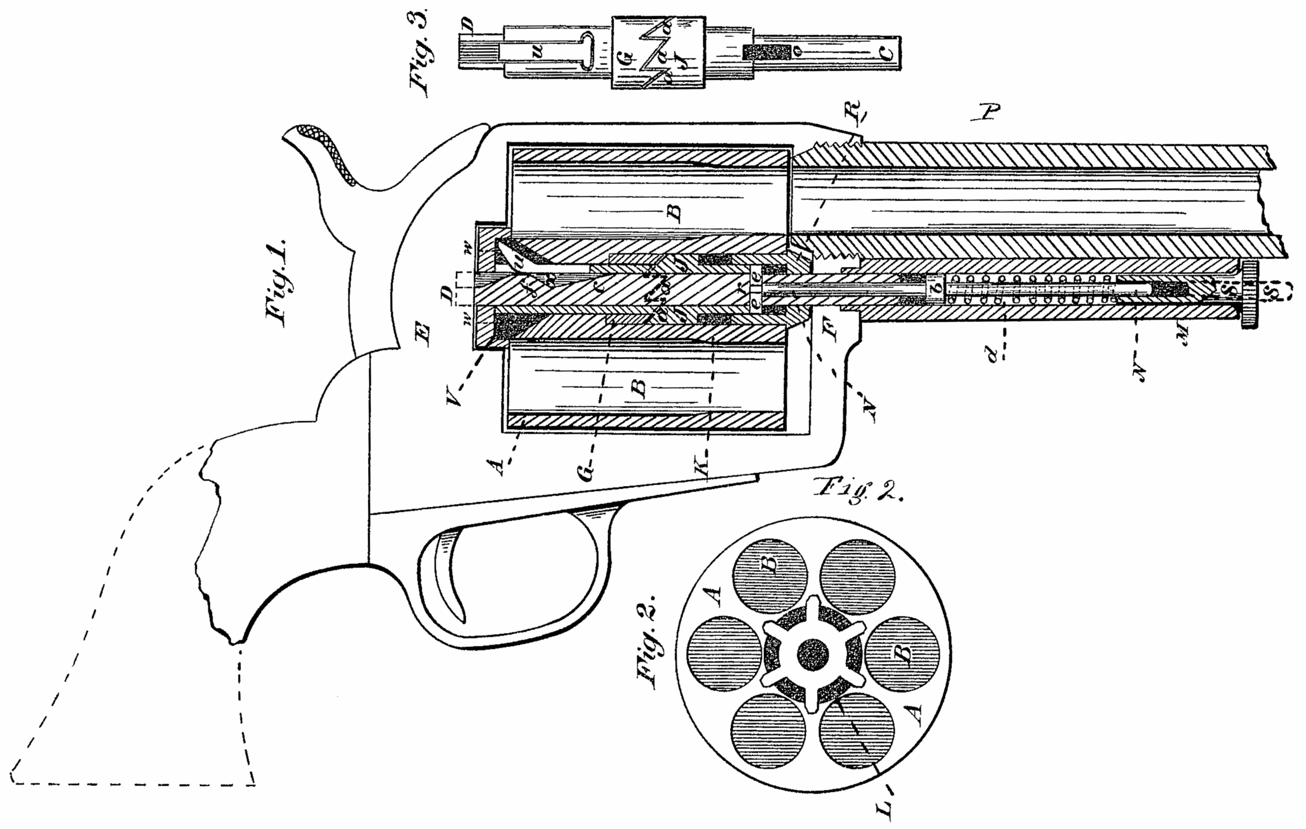
Figure 1 represents a central longitudinal section thereof through a revolving pistol having my improvement applied thereto; Fig. 2, an end view of the revolving cylinder there of; Fig. 3, a side elevation of the ejecting device for expelling the empty shells from the chambers of the cylinder.
My invention consists in a suitably-constructed device for ejecting empty shells from the chambers of revolving fire-arms when operated by turning or revolving the cylinder thereof.
The frame, barrel, and lock of a revolving pistol being no part of my invention, only such portions thereof are represented in the accompanying drawings as are necessary to illustrate the new device for ejecting the empty shells from the chambers by the act of turning the cylinder, which constitutes my present invention.
A represents the cylinder of a revolving pistol, having the usual number (six) of chambers B, for the reception of the ordinary metallic cartridge. To this revolving cylinder is fitted the ejecting device for discharging the empty shells therefrom, one form of which consists in the following mechanism, operated in the act of turning said cylinder: The journal or central pin c, which supports the cylinder A, and upon which it revolves, is station. ary, its rear end D extending into and resting in a recess in the frame E, while the front end thereof extends through the front side F of the yoke-frame of the arm, thus forming the two bearings of the cylinder, to permit it to revolve freely upon its pin c. About the middle of this cylinder, and in an enlarged part thereof, and in the central opening for the pin c, is fitted a bushing, G, having ratchet-teeth a formed upon one end thereof, corresponding in number with the number of chambers B in the cylinder. This bushing is securely fastened within the chamber, and revolves therewith. Corresponding with this notched bushing G is a sliding notched collar, J, which does not revolve with the cylinder and its fixed bushing G, but slides back and forth in the space K by means of the corresponding ratchet-teeth C as the cylinder is turned or revolved. To prevent this sliding notched collar J from revolving with the cylinder, the upper end thereof is recessed, so as to receive a pin, e, which passes through a slot, o, in the stationary center pin c, and is retained in position by the end r of a spring-rod, N. This spring-rod N extends from the cross-head pin r, along the lower side of the barrel P, a sufficient distance to receive a coiled spring, d, around it, one end of which bears against a collar, b, formed thereon, and the other end rests against a sliding thumb-piece, s, which thumb-piece is operated longitudinally with the barrel to compress the spring d, to obtain sufficient force to eject the shells. To receive and maintain in position this spring-rod N and sliding thumb-piece, and in which they both operate, a tubular guide, M, is provided, which is firmly secured to the lower side of the barrel in any convenient manner.
Having produced within the cylinder (and by its action) the required sliding movement, an ejecting-piece, u, is pivoted to the inner end of the sliding collar J, which operates back and forth and up and down in a recess, v, formed in the rear end of the cylinder to eject the empty shells. To obtain the necessary up-and-down movement of the outer end or toe of this ejecting-rod, in order to pass over the ratchet or teeth by which the cylinder is revolved, the central pin c is recessed longitudinally, and notched or beveled at x, so that, as the bushing J is withdrawn or raised by means of the corresponding notches and teeth a, the heel of the ejecting-rod at drops down into this recess x; and when this sliding bushing or collar J is again driven forward by means of the spring-bar N, in revolving the cylinder, the toe of the ejecting-rod moves up the inclined plane f in time to bring it directly behind the rims or flanges of the shells, and by the force of the spring d eject them from their chambers, the end of the ejecting-rod operating through the openings L between the ratchet-teeth w of the cylinder.
While firing the arm it is preferable, though not necessary, that the spiral spring d should not operate with its full force against the sliding collar and ejecting device pivoted thereto. Therefore, to relieve the tension of this spring a thumb-piece, s, is arranged in the front end of the guide tube M, which slides back and forth in a suitably-formed slot therein, having a notch at one side to receive a lug when its full force is exerted to eject the shells. Thus, when the empty shells are to be ejected from the chambers of the cylinder, the sliding thumb-piece s compresses the spring around. the sliding rod N, thereby forcing the teeth of the collar J firmly against the corresponding teeth of the revolving bushing G, so that, as each chamber containing a shell to be ejected is brought into position, the ejector u is raised, and its end or toe sharply driven against the flange of a shell, causing it to be thrown out of and clear from its chamber.
To prevent the front end of the cylinder bearing with too much force against the rear end of the barrel, a bushing, R, is provided, the shank of which extends a distance into the front end thereof, which front end rests against a shoulder on the projecting head of said bushing, as represented in section, Fig. 1, the face of this head bearing against the frame F.
If desired, the spring-rod N may project beyond the face of the thumb-piece s, as represented in dotted lines, Fig. 1, so that in case a shell should stick in its chamber, and not be removed therefrom by the action of the spring upon the ejector, it may be forced out by pressing upon this projecting end, which would operate the same as though there were no spring, and thus becomes a positive-acting ejector.
I wish to be distinctly understood that I do not confine myself to the exact construction and arrangement of mechanism herein described, and represented in the accompanying drawing, for ejecting the empty shells from the chambers of revolving fire-arms, but in tend to embrace, as equivalents therefor, such device or devices for the purpose set forth, when operated by the act of revolving or turning the chamber, substantially as herein described.
Having thus fully described my improved ejecting device for revolving fire-arms, what I claim as new, and desire to secure by Letters Patent, is-
In a revolver, an automatic ejector, adapted to be operated by the rotation of the cylinder independently of the firing mechanism, substantially as herein set forth and described.
STEPHEN W. WOOD.
Witnesses:
COLBORNE BROOKES,
F. W. FARLEIGH.