
US 547525
UNITED STATES PATENT OFFICE.
FREDERICK SMITH, OF WORCESTER, MASSACHUSETTS, ASSIGNOR TO THE HARRINGTON & RICHARDSON ARMS COMPANY, OF SAME PLACE.
EJECTOR FOR REVOLVERS.
SPECIFICATION forming part of Letters Patent No. 547,525, dated October 8, 1895.
Application filed June 19, 1896. Serial No. 553,263, (No model.)
To all whom it may concern:
Be it known that I, FREDERICK SMITH, a citizen of the United States, residing at Worcester, in the county of Worcester and State of Massachusetts, have invented a new and useful Improvement in Ejectors for Revolvers, of which the following, together with the accompanying drawings, is a specification sufficiently full, clear, and exact to enable persons skilled in the art to which this invention appertains to make and use the same.
This invention relates to an improved construction of the ejector-actuating devices or means for catching and releasing the hook-plate as the barrel is tilted forward, the object being to afford a simple and efficient construction that can be manufactured with economy and practical facility; also to provide a radially-reciprocating catch-stud supported within the hook-plate, together with a coiled spring therefor, and adapted for operation in conjunction with the barrel and frame in the specific manner set forth; also, to combine the catch-stud and spring devices with the hook-plate in permanent assemblage, thereby obviating liability of displacement or loss when the arm is unjointed for cleaning or repair.
These objects I attain by a mechanism embodying the peculiar construction shown in the drawings, wherein—
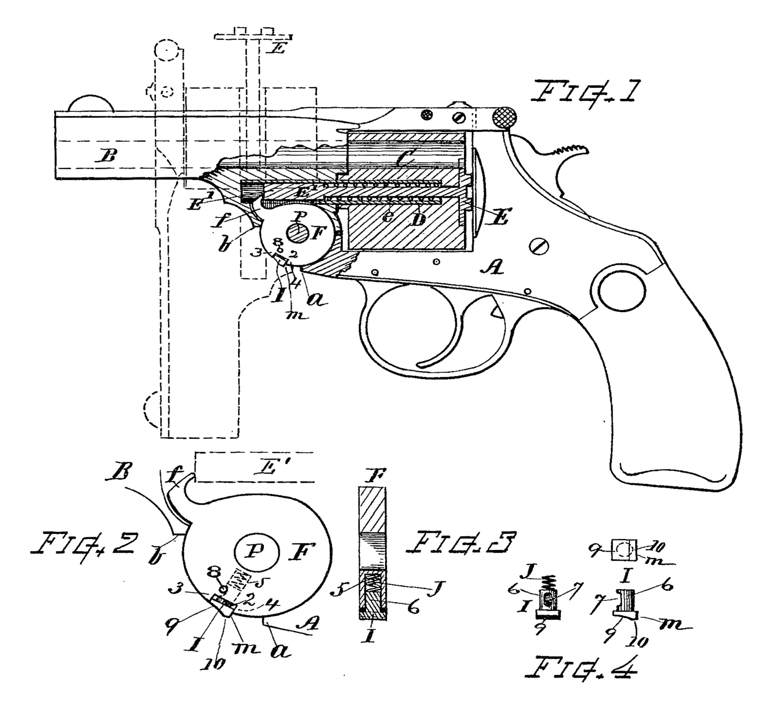
Figure 1 is a part side part sectional view of a revolver embracing my improvement. Fig. 2 is an enlarged side view of the hook-plate and stud. Fig. 3 is a section transverse of the same, and Fig. 4 shows details of the stud separate from the hook.
Referring to parts, A denotes the frame of the revolver; B, the barrel, hinged to the fore-end of the frame at P to tilt forward in usual manner; C, the cylinder, mounted on the non-rotatable tubular spindle D; and E, the ejector, having the stem E’ and return-spring e, all of which parts may be of suitable or well-known construction.
F indicates the hook-plate, arranged in the center of the hinge between the barrel-ears and pivoted on the hinge-pivot P, said plate having the usual integral hook f projecting from its periphery for engaging the end of the ejector-stem E’. In accordance with my invention this hook-plate is formed with a rectangular notch or recess 2, extending across its periphery at the position shown, the upper and lower ends of said recess terminating with parallel shoulders 3 and 4, while the bottom of the recess is preferably straight and square between said shoulders. A radially-disposed hole 5 is drilled from the bottom of the recess toward the center axis. Within this recess I arrange a square-headed stud I, having a shank 6, that enters the hole 5, while the head of the stud fits the recess 2 and fills the space between the parallel shoulders 3 and 4 closely, but in a manner to move freely therein. The width of the head is of the same dimension as the thickness of the plate. Sufficient space is provided in the recess beneath the head of the stud to allow its movement for retracting the head wholly within the limit of the peripheral circle of the hook-plate, and an expanding spiral spring J is arranged in the inner part of the hole 5, which spring acts against the stud and normally presses it outward, the stud being thus adapted for reciprocal movement ina direction radial to the circle of the hook-plate. One side of the shank 6 is cut away, as at 7, for a suitable space, and the stud is retained in the hook-plate and limited in its movement by a small retaining-pin 8, that passes through the hook-plate and engages the cut-out space 7, as indicated. The outer end of the stud is fitted with an incline or outwardly-curved cam-surface 9, which normally stands at the shoulder 3, flush with the peripheral surface of the hook-plate and terminating near the opposite part of the head in a narrow surface 10, formed flat or concentric with the circle of the hinge-ears. At the lower part of the head the stud normally projects beyond the peripheral circle and presents an edge or shoulder m for catching upon the shoulder a at the fore-end of the frame.
In the operation when the barrel is unlatched and tilted forward the projecting edge m of the stud I moves into contact with the shoulder a at the end of the frame. This arrests the movement of the hook f, causing it to force outward the ejector E (see dotted line, Fig. 1) as the barrel is further tilted. When the shoulder b of the barrel approaches the end of the frame, said shoulder acts against the incline or cam-surface 9 and, in opposition to the spring J, forces the stud inward until its end 10 is brought within the peripheral circle or so that it can pass within the hinge-chamber at the bottom of the frame, thus disengaging its edge m from the shoulder a and releasing the hook-plate F and its hook f. Then the ejector is immediately returned to its normal position by the force of the ejector return-spring e in well-known manner. When the barrel is tilted back to its normal position and the stud I swings outward past the end frame, the stud is reciprocated to its normal position by the coiled spring J, acting against the inner end of its shank 6. If it is desired to drop the ejector before the full tilting of the barrel, it can be done by pressing in the stud with the thumbnail.
Among the advantages incident to the specific construction of actuating devices as herein shown and described may be mentioned its simplicity and efficiency, its economy and facility of manufacture, requiring but few and convenient operations for making aud fitting the hook-plute and stud in combination; when assembled the stud and spring, being securely retained in the hook-plate, do not drop out of place with liability of becoming lost when the revolver is taken apart for cleaning, &c.; its strength and durability and precision in operation, as the parallel shoulders give close support to the head of the stud, while it acts by a direct radial reciprocative movement and is not subject to derangement or breakage either of the stud or its spring.
I claim as my invention and desire to secure by Letters Patent—
1. An improved ejector operator for revolvers, comprising the radially reciprocating stud having a rectangular head, an inclined end face and cylindrical shank with a recess on the side thereof, the hook-plate carrying the ejector-elevating hook, said hook-plate having a radial hole that receives the shank of said stud, and at its periphery a transverse rectangular recess with square parallel shoulders that embrace and support the head of said stud, the coiled spring for projecting said stud, and the retaining pin arranged in the plate, as set forth.
2. In an ejector mechanism for revolving fire arms, the hook-plate having the rectangular transverse recess and inwardly extending hole therein, the square-headed stud arranged in said recess with its shank inserted in said hole, the outer end of said stud having an outwardly inclined or curved surface and an engaging edge, the coiled spring disposed within said hole for exerting outward pressure on said stud, and the retaining-pin passing through the hook-plate and engaging in a recess in the side of the stud; in combination with the ejector, the frame having the fore-end shoulder and the barrel having the hinge, as set forth.
Witness my hand this 15th day of June, 1895.
FREDERICK SMITH.
Witnesses:
CHAS. H. BURLEIGH,
ELLA P. BLENUS.