
US 552699
UNITED STATES PATENT OFFICE.
WILLIAM A. RICHARDSON, OF WORCESTER, MASSACHUSETTS.
DISCHARGING MECHANISM FOR FIREARMS.
SPECIFICATION forming part of Letters Patent No. 552,699, dated January 7, 1896.
Application filed April 1, 1895. Serial No. 543,953. (No model.)
To all when it may concern:
Be it known that I, WILLIAM A. RICHARDSON, a citizen of the United States, residing at Worcester, in the county of Worcester and State of Massachusetts, have invented a new and useful Improvement in Discharging Mechanism for Firearms, of which the following, together with the accompanying drawings, is a specification sufficiently full, clear, and exact to enable persons skilled in the art to which this invention appertains to make and use the same.
My present invention relates to the peculiar construction of the firing-pin and to the manner of combining the same with the frame and hammer in a revolver or other firearm, the objects being to afford a simple and desirable structure that can be manufactured with practical economy and conveniently assembled; also to render the firing mechanism more efficient and capable of operation with light impact and a greater degree of certainty in its action upon the primers. These objects I attain by the mechanism illustrated in the accompanying drawings, wherein—
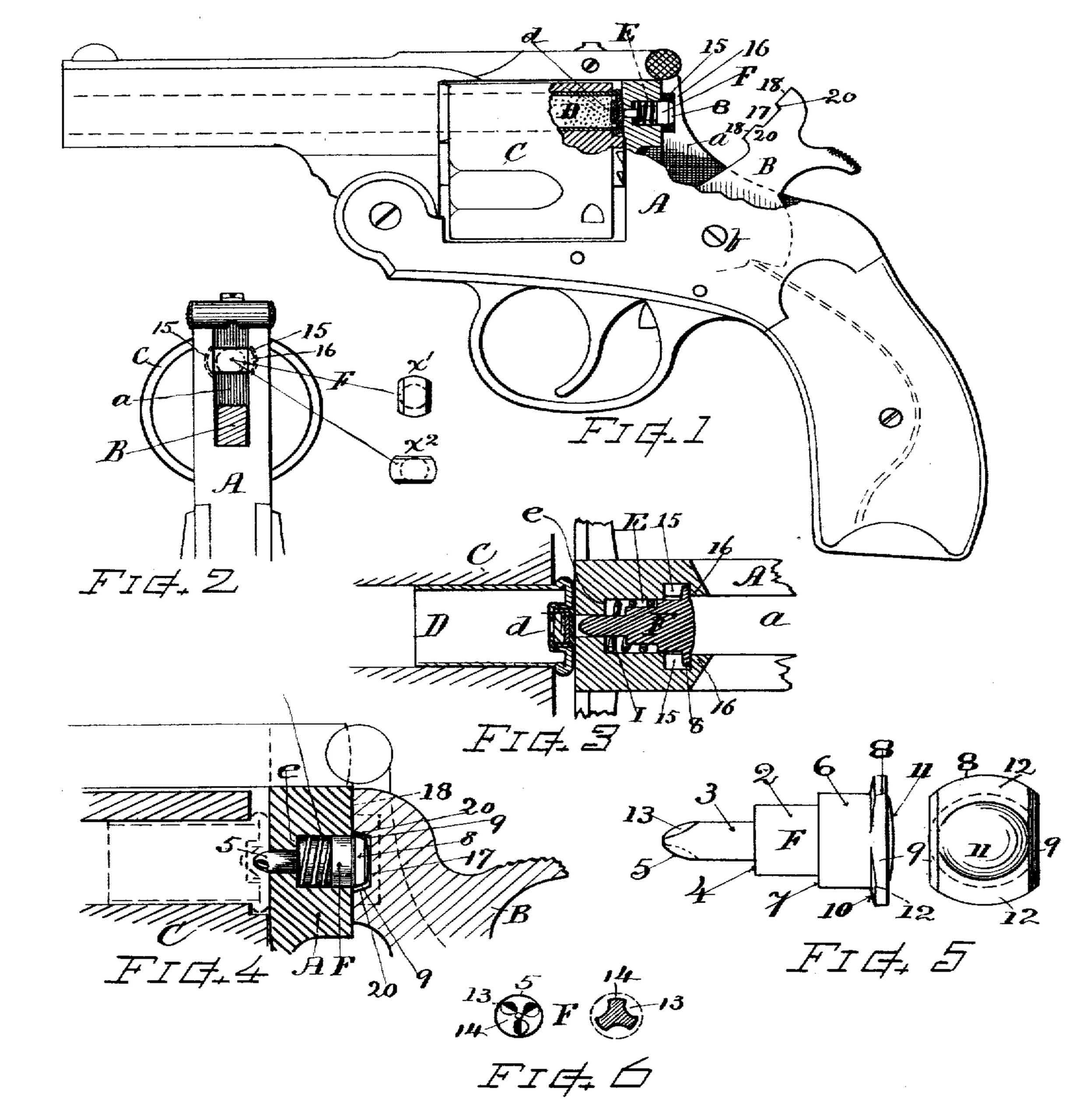
Figure l is a side view, partly in section, showing my invention applied to a revolver. Fig. 2 is a transverse sectional view showing the upper part of the frame and the firing-pin from the rear, and the positions of the firing-pin head. Fig. 3 is a section horizontally through the firing-pin and frame on an enlarged seal e. Fig. 4 is a vertical section showing the firing-pin and adjacent parts with the firing-pin projected forward. Fig. 5 shows, on larger scale, the form of the firing-pin in detail. Fig. 6 shows an end view and a transverse section of my improved point for firing pins.
My improvements are applicable to discharging mechanism in other styles of firearms, as well as for revolvers, the construction and arrangement of the firing-pin and operating parts being substantially the same as herein described.
Referring to parts, A denotes the frame having the slot a and contact-seat therein for the hammer B, which latter is pivoted in the frame at b to swing back and forward in usual manner, it being operated by a suitable main- spring and trigger mechanism, which parts may be of well-known or any suitable kind.
C indicates the cylinder, also of well-known structure and operated by the usual or any suitable means.
D indicates the cartridge in the cylinder chamber or bore, having the primer d in position ready for discharge.
F indicates the firing-pin, which in accordance with my invention is constructed and combined for operation as here explained in detail. This firing-pin is formed with a central body portion 2, having at one end an inward offset or shoulder 4, and forwardly-extending smaller front bearing portion 3 terminating in a conoidally-rounded point 5 adapted for indenting the primer d. At the other end of said body portion 2 there is formed an outward offset or spring-seating shoulder 7 and a larger rear bearing portion 6, upon the rear end of which I provide an oblong head or opposite side flanges 8 that project beyond the cylindrical surface of the portion 6, externally perpendicular to the axis of the pin. Two sides of the head are cut away parallel with each other and to the same dimension as the diameter of the part 6, the edges at 9 being preferably inclined or beveled rear-wardly inward, as indicated.
The inner face 10 of the flanged head is slightly inclined backward, so that the outer part of the flange is a little thinner than the part next the bearing portion 6. The inclined front surface 10 of the flanges 8 contacts with the striker seat or surface on the frame to arrest the movement of the firing-pin when it is thrown forward, as when snapping the lock with the cylinder open or uncharged; and by making such surface inclined, as at 10, the contact and shock is caused to act at position close to the body of the pin, and the outer edge of the flanges are relieved from the shock or resistance, thus obviating liability of the head-flanges being scaled off by constant snapping of the lock mechanism. On its outer end face the pin has a slightly rounded boss 11, leaving flat marginal surfaces 12 on the rear of the head-flanges 8, as shown. The body portions 2, 3, and 6 are cylindrical in cross-section.
The conoidal point 5 of the firing-pin is best formed with a series of grooves or fluting 13, preferably three, cut into the rounded surface thereof, commencing near the apex and extending longitudinally through the swell of the conoidal portion, (see Figs. 5 and 6,) thereby reducing the rounded surface and shaping the point with a series of small ridges 14 having the conoidal contour and with intermediate relieving-spaces 13, thus adapting the point 5, when indenting the primer d, to draw or press in the metal with greater ease and efficiency, so that the primer can be exploded with a lighter stroke of the hammer B; also giving greater certainty of action and requiring less spring-tension for throwing down the hammer. Consequently a more easily worked mechanism can be produced. This formation also prevents the adhering of the point in the primers, and enables the firing pin to be more easily and certainly retracted by the retracting-spring. This peculiar formation of the point of the firing-pin is a feature of my invention, and may be successfully employed on firing-pins in other firearm structures than that herein shown.
The opening E in the frame A for the reception of the firing-pin F is formed as a circular hole having a diameter at its rear end the same or somewhat less than the width of the hammer-slot a, such diameter corresponding with that of the larger bearing portion 6 of the firing-pin, while the forward part of said opening corresponds with the diameter of the smaller bearing portion 3 of the firing-pin. A shoulder e is formed within the opening, leaving sufficient metal about the point or smaller part of the opening to give ample strength and support to guide the pin and to withstand the firing service without material breaking out or deterioration.
Within the frame, at the sides of the hammer-slot a, at positions adjacently coinciding with the firing-pin, I form under-cut lateral recesses 15, the lateral dimension of which is sufficient to receive the firing-pin-head flanges 8, while the dimension of said recesses from front to rear equals the thickness of said head flanges 8 plus the extent of movement of the firing-pin action, so that when the head is pressed back against the frame-lip 16 the point of the pin will be retracted within the frame. (See Fig. 3.) A spring I is arranged within the opening strained between the shoulders e and 7 for retracting the firing-pin F.
The contact-face of the hammer B has a recess 17 for accommodating the firing-pin head and is fitted with flat surfaces 18 that strike the seat or square portion of the frame A above and below the firing-pin, the recess allowing said firing-pin slight free space when the hammer-face 18 strikes the seat or solid frame. This avoids injuring or breaking the flanges 8 of the firing-pin.
Inclines 20 are provided on the hammer-face, that match the inclined surface 9 on the firing-pin head. Such inclines serve in conjunction to keep the firing-pin in proper position or to bring its oblong head into square transverse relation with the side recesses in case it becomes slightly deviated therein.
When assembling the paris the firing-pin is introduced into its opening E through the hammer-slot a with its oblong flanged head in upright position, as at x’, Fig. 2. Then, when entered, it is turned or partially rotated so as to bring the oblong head into horizontal position, as at x2, thus carrying the side flanges 8 into the recesses 15, whereby the firing-pin is confined by the flanges 8 engaging under the lip or overhanging part 16 of the frame. The flanged head of the firing-pin is allowed ample movement forward and backward within the recess for effecting the discharge of the primer when the hammer falls. The spring I normally presses the firing-pin back, so that its flat portion 12 rests against the lip 16 when the hammer is raised. Hence there is no tendency for the firing-pin to rotate out of position; but it can at any time be removed by turning its head upright in the hammer-slot.
What I claim as of my invention, and desire to secure by Letters Patent, is—
1. In a fire-arm, the combination of the frame having lateral under-cut recesses at the sides of the hammer-seat and the firing-pin having an oblong head or side flanges that engage with said recesses, for the purpose set forth.
2. In a fire-arm, the frame having the hammer-slot therein, an opening through the hammer-seat of less diameter than the width of said hammer-slot, and lateral under-cut recesses from said hammer-slot formed in the sides of the frame adjacent to said opening, in combination with the firing-pin adapted to be entered through said hammer-slot and haying side flanges that engage within said recesses; a spring for retracting said firing-pin, and the hammer having its contact face filled for striking the firing-pin and the hammer seat on the frame, as set forth.
3. The firing-pin provided with the laterally oblong head, the parallel edges of said head beveled, as at 9, in combination with the hammer having, in its contact face 18, a recess 17 formed with inclined end surfaces 20 that embrace said beveled edges upon the firing-pin head, for the purpose set forth.
4. The firing-pin provided with projecting flanges upon its head, and having the front surface 10 on said flanges formed backwardly inclined, in combination with the striker-seat having an opening in which said firing-pin is supported for the purpose set forth.
5. A firing-pin having its head formed with projecting flanges 8, the central end surface of the head bossed or slightly rounded outward, as at 11, and the rear side 12 of said flanges formed flat on a plane perpendicular to the axis of the firing-pin, in combination with the hammer and the frame having the hammer-seat, the under-cut side recesses 15 and the retaining lips 16 against which said flanges are supported.
6. A firing-pin for fire-arms, having a conoidally rounded point provided with a series of flutings in its indenting end surface.
7. A firing-pin for fire-arms, provided with a conoidally rounded point, having its rounded surface reduced by depressions or cut-away spaces extending from near the apex back through the swell of the conoidal portion, and with full ridges forming the rounded conoidal end surface between such reduced spaces, substantially as and for the purpose set forth.
Witness my hand this 29th day of March, A. D. 1895.
WILLIAM A. RICHARDSON.
Witnesses:
CHAS. IT. BURLEIGH,
ELLA P. GLENS.