
US 635705
UNITED STATES PATENT OFFICE.
JOSEPH H. WESSON AND JOHN L. HOBBS, OF SPRINGFIELD, MASSACHUSETTS; SAID HOBBS ASSIGNOR TO SMITH & WESSON, OF SAME PLACE.
SAFETY DEVICE FOR REVOLVING FIREARMS.
SPECIFICATION forming part of Letters Patent No. 635,705, dated October 24, 1899.
Application filed August 18, 1899. Serial No. 727,641. (No model.)
To all whom it may concern:
Be it known that we, JOSEPH H. WESSON and JOHN L. HOBBS, citizens of the United States of America, residing at Springfield, in the county of Hampden and State of Massachusetts, have invented new and useful Improvements in Safety Devices for Revolving Firearms, of which the following is a specification.
This invention relates to revolving firearms, and has for its object an improved construction of certain lock parts of revolver-pistols whereby the arm cannot be cocked while the cylinder is misplaced and the firing of the same cannot take place when the cylinder-chambers are not in line position relative to the barrel, thus obviating accidents which otherwise might occur without the preventives herein provided; and the invention consists in the peculiar construction and arrangement of said lock parts, all as hereinafter fully described, and more particularly pointed out in the claims.
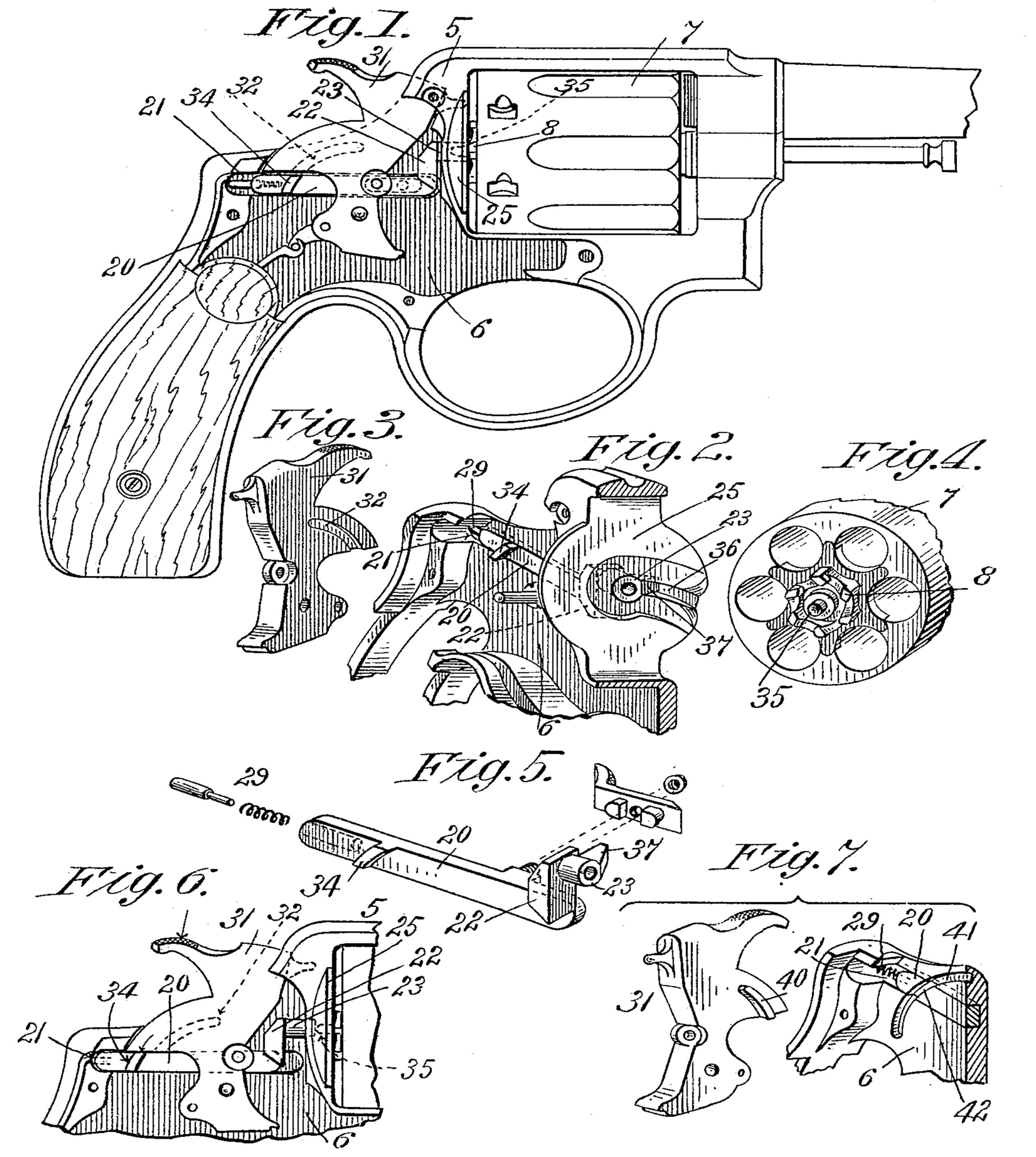
In the drawings forming part of this specification, Figure 1 is a side elevation of a revolver-pistol having the side plate of the arm removed and illustrating our improvements in assembled positions. Fig. 2 is a perspective view of the upper part of the frame of the arm, showing the face of the recoil-plate and the safety-bolt. Fig. 3 is a perspective view of the hammer, showing the side thereof which moves opposite the inner side of the frame. Fig. 4 is a perspective view of the rear end of the cylinder shown broken off from the opposite end. Fig. 5 is perspective view of the safety-bolt and rear cylinder support or bearing thereon, together with the finger-piece therefor. Fig. 6 is a side elevation of a portion of the frame of the arm on which the hammer is hung, and of the hammer, and illustrating the relative positions of said parts. Fig. 7 illustrates a modified construction of the hammer, a part of the frame of the arm, and of said safety-bolt, all of which are below described.
Referring to the drawings, 5 indicates the frame of the arm, on which is the usual recoil-plate 25, and 6 the inner side of the frame, in which is a safety-bolt groove 21. The cylinder 7 has the usual ratchet 8 on its rear end, with which the usual pawl (not shown) engages for rotating the same. The hammer is indicated by 31. The frame of the arm is generally of the usual type, excepting in so far as it is provided with the said groove 21, which is formed in the inner side of that part 6 thereof intermediate of the stock and the recoil-plate 25, and the latter is provided with a radial groove 36, in which the rear end of the cylinder center-pin 85 moves when the cylinder swings to firing position in the frame, and at this time the safety-bolt 20, on which is a head 22, carrying a cylindrical socket 23 for receiving the projecting end of the said pin, is either moved rearward by the impact of the point of said center-pin there against or is drawn back by the finger to the position shown in Fig. 6, and upon freeing said bolt a spring and plunger 29 in the rear end thereof act to slide it to the position shown in Figs. l and 2, wherein said socket 23 is caused to receive the rear end of said center-pin, as shown in Fig. 1, thereby holding the cylinder in firing position, and when thus held the arm may be safely discharged; but should there be some obstruction whereby the cylinder and the safety-bolt should not become interengaged, as above described, the herein described improvements in the construction of the hammer and said safety-bolt so act as to prevent the firing of the arm before the said pin and socket shall be properly engaged. The said radial groove 36 in the recoil-plate 25 extends from the border of the latter to an opening through the center thereof, having a conformation (the center of which is cylindrical) conforming in size to the shape of said socket 23, which, as aforesaid, receives the rear extremity of the said center-pin 35 of the cylinder, and laterally from said cylindrical opening is a short slot extending in line with said radial groove 36. Thus an opening is formed in the center of the recoil-plate 25 to receive said socket and a short branch 37, extending therefrom toward the inner end of said slot. The side of said branch 37 adjoining the cylinder is tapered or of wedge form, as shown in Fig. 5, and presents its thin outer end in a plane with the base of said radial groove 36 (see Fig. 2) to the end that the end of said center-pin 35 shall when the loaded cylinder is swung into the frame in firing position engage the said tapered or inclined branch and drive said bolt rearward to such degree that the end of said center-pin shall come freely opposite said socket, and upon reaching such position said spring 29 drives said bolt forward, and it takes the proper firing position. (Shown in Fig. 1.)
The side of the frame on which the bolt 20 slides in the groove 21 has a slot through it, letting a screw-stud 26 project through it, whereby the finger-piece 28 for operating the slide from the outside is secured to the bolt by a nut. (Shown in Fig. 5.) Two studs on said finger-piece are thus brought to a bearing on the bolt, and the finger-piece is thus firmly supported. The said safety-bolt 20 and the hammer 31 are provided with coacting means whereby, should said bolt be from any cause prevented from sliding forward to said cylinder-pin-engaging position, when loaded for firing or otherwise, the hammer cannot be operated to explode a cartridge, and said bolt and hammer devices are constructed and operated as follows: By referring to the drawings it will be seen that the hammer 31 has a radial groove 32 in the side thereof adjoining the side of the frame 5 of the arm, in which the safety-bolt 20 moves, and that the said bolt has a circular segment 54 thereon, which when the bolt is in proper position, as in Fig. 1, is engaged by said hammer slot or groove 32 during the movements of the hammer in cocking it or in firing the arm; but should any obstacle prevent the full engagement of said bolt-socket 23 and the end of the cylinder-pin 35 said bolt-segment 34 will be held in such position to one side of said hammer-groove 32 that a part of the hammer, one side of said groove, as shown in Fig. 6, will so engage said segment 34 that the hammer cannot be cocked to fire the arm; but on adjusting the safety-bolt and the cylinder to mutually-operative firing positions the hammer will work freely.
Fig. 7 illustrates a modification consisting of a reversal of the locations of said segment 34 and radial groove 32, wherein a groove 41 is formed in the side of the frame and a like groove 42 is formed in the safety-bolt 20 and the hammer is made with a projecting rib segment 40 to move in said grooves.
Having thus described our invention, what we claim, and desire to secure by Letters Patent of the United States, is—
1. Safety devices preventing the firing of revolving firearms when the cylinder is not in firing-line with the barrel, comprising a spring-actuated bolt having a cylinder-pin socket on one end projecting through the recoil-plate, which constitutes a support for the rear end of the cylinder when in firing position, a hammer swinging at the side of said bolt, and means intermediate of said bolt and hammer whereby the arm is rendered unserviceable while said cylinder-pin and socket are disengaged, substantially as described.
2. Safety devices preventing the firing of revolving firearms when the cylinder is not in firing-line with the barrel, comprising a spring-actuated bolt having a cylinder-pin socket on one end projecting through the recoil-plate, which constitutes a yielding support for the rear end of the cylinder-pin, a hammer swinging at the side of said bolt, having a groove therein, and a projection on said bolt normally engaging said groove, but engaging the hammer and preventing the firing of the arm, should said cylinder-pin and socket be not operatively engaged, substantially as described.
3. Safety devices preventing the firing of revolving firearms when the cylinder is not in firing-line with the barrel, comprising a bolt supported for endwise movement between the hammer and the adjoining side of the frame of the arm having a head on which is the socket 22 and branch 37, a spring foreing said bolt toward the recoil-plate, an opening in the recoil-plate receiving said branch and socket, whereby the latter constitutes a support for the rear end of the cylinder when in tiring position, a hammer swinging at the side of said bolt having a groove therein, and a projection on said bolt normally engaging said groove, but engaging the hammer and preventing the firing of the arm, should said cylinder-pin and socket be not operatively engaged, substantially as described.
4. Safety devices preventing the firing of revolving firearms when the cylinder is not in firing-line with the barrel, comprising a bolt having a head on which is the socket 22, and branch 37, an opening in the recoil-plate receiving said branch and socket, whereby the latter constitutes a support for the rear end of the cylinder when in firing position, a hammer swinging at the side of said bolt having a groove therein, and a projection on said bolt normally engaging said groove, but engaging the hammer and preventing the firing of the arm, should said cylinder-pin and socket be not operatively engaged, substantially as described.
JOSEPH H. WESSON,
JOHN L. HOBBS.
Witnesses:
H. A. CHAPIN,
K. I. CLEMONS.