
US 7596
UNITED STATES PATENT OFFICE.
NATHAN B. COOK, OF CHICAGO, ILLINOIS.
IMPROVED LOCK FOR FIRE-ARMS.
Specification forming part of Letters Patent No. 7,596, dated August 27, 1850.
To all whom it may concern:
Be it known that I, Naruan B. Coox, of the city of Chicago, in the county of Cook and State of Illinois, have invented a new and useful Improvement on a Lock for Fire-Arms; and I do hereby declare that the following is a full and exact description of the construction and operation of the same, reference being had to the accompanying drawings, making a part of this specification, in which—
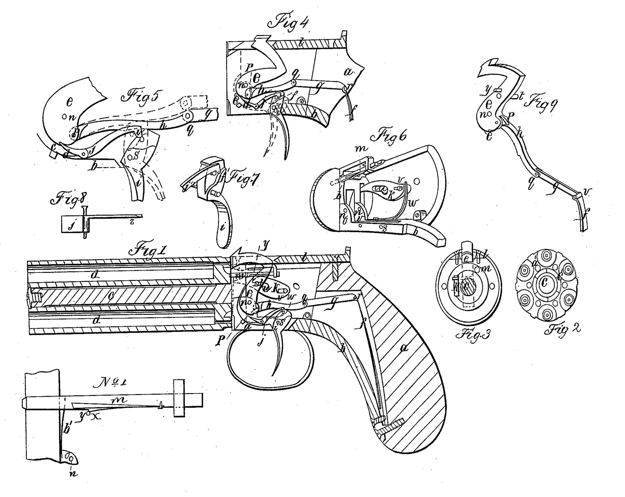
Figure 1 represents a longitudinal section of a revolving pistol; Fig. 2, the breech end of the barrel; Fig. 3, the front of the breech; Fig. 4, a section of the lock, showing the hammer at cock; Fig. 5, a section of the lock, showing the hammer at cock and held in its position by the sear when it is to be operated as a hair-trigger; Fig. 6, a section of the lock in perspective, showing the ratchet-lever and sliding bolt which retains the barrel in its position; Fig. 7, a perspective view of the trigger and part of the spring-lever of the sear; Fig. 8, an under side view of the sear; Fig. 9, a perspective view of the hammer and the bar and swivel by which the mainspring is connected with the hammer.
a, Fig. 1, represents the stock; b, the trigger-plate; c, the spindle upon which the barrel revolves; d d, the barrels; e, the hammer; f, the mainspring; g, the swivel; h, the bar upon which the trigger acts to force the hammer back; i, the trigger; j, the sear; k, the ratchet-lever; l, the top cap and sight; m, the sliding bolt which holds the barrel in its position, the whole, excepting the stock, being constructed of steel or other suitable metal.
The operation of the lock is as follows: When at rest, as shown in Fig. 1, with the hammer pressing against the cap on the nipple of the upper barrel d, the trigger i having its upper end against the notch in the under side of the bar h, the cam i’ on the end of the spring-lever of the sear resting on the pin near the top of the trigger, the end of the bolt m pressed in the hole a’ in the breech of the barrel, Fig. 2, by the spring b’, No. 1, the end of the ratchet-lever a little above the notch c’ on the breech end of the barrel, Fig. 2, therefore if the trigger be pressed with the finger in the direction of the stock a, working on the pivot s, the upper end of the trigger presses against the notch in the under side of the bar h and forces it forward, which causes the hammer e to revolve on the axis n until it comes in the position shown at Fig. 4; also, at the moment when the hammer begins to move the pin y (shown in Figs. 1 and 9) intercepts the notch in the spring on the sliding bolt at x, No. 1, and draws it back, thereby releasing the barrel, which is immediately made to revolve by the ratchet-lever k, which is pressed downward by the pin t in the hammer working in the slot u. The barrel, being revolved until the next nipple is brought in the proper position, is again held by the bolt m. The cam i’ passes over the pin in the upper part of the trigger, and drops into the position shown in Figs. 4 and 7. The sear, being pressed upward by the spring d’, passes into the notch e’ in the lower part of the hammer. This movement also raises the bar h and the swivel g, bringing the joint q above a right line from the joints p and r, causing a pressure of the bar h upon the top of the trigger. Then if the pressure of the finger be removed from the trigger, the sear j holds the hammer in the position shown Figs. 4 and 5, while the pressure of the bar h upon the top of the trigger will bring it in the position shown in Fig. 5 and by the dotted lines in Fig. 4. At the same time the trigger, in passing back to the position shown in Fig. 5, brings the pin on its side in contact with an inclined plane on the inside of the cam i, (shown at z, Fig. 8,) and bending the spring outward passes by it, and the cam comes into the position shown in Fig. 5 and by the dotted lines in Fig. 4, resting on the pin on the side of the trigger. Now if the finger be pressed slightly upon the trigger, the pin on the side of the trigger raises the lever of the sear and disengages the sear from the notch in the lower part of the hammer, which, being at liberty to be acted upon by the main-spring, is brought down upon the nipple and the piece is discharged. When it is desirable to fire with more rapidity, the hammer is brought, as before, into the position shown at Fig. 4, when, instead of removing the finger from the trigger, the pressure is continued in the direction of the stock a, when the curved shoulder f’ on the side of the trigger, Fig. 7, comes in contact with the cam i’, and forces the lever of the sear upward, removing the sear from the notch in the lower part of the hammer. At the same time, the top of the trigger, being slightly eccentric, raises the bar h upward, as shown by the dotted lines in Fig. 5, and thereby disengages itself from the notch in the under side of the bar h, and the hammer, being acted upon by the mainspring, is brought down upon the nipple and the piece is discharged.
The nature of my invention consists in the fact that I so construct and arrange the machinery of the lock of a revolving or other fire-arm that by pressing upon the trigger with the finger the hammer is brought back to cock, and the finger may then be removed and the trigger allowed to pass forward, while the hammer is retained in its position by the sear, and may then be discharged by a light touch of the finger upon the trigger, enabling the operator to fire with all the ease and steadiness secured by the use of the hair-trigger, or admitting of being fired, when expedition is desired, by one continuous pull or pressure of the finger upon the trigger.
What I claim as new, and desire to secure by Letters Patent, is—
The sear j, in combination with the pin and shoulder on the trigger, by which arrangement the hammer, after being brought back by the pressure of the finger upon the trigger, is held in its position by the sear, while the trigger passes forward, and the piece is discharged by a light touch of the finger upon the trigger, securing deliberation and certainty of aim, or may be discharged by one continuous pressure of the finger upon the trigger, at the pleasure of the person using the same; and in this claim I wish to be understood that I do not confine myself to the precise arrangement of the parts herein described, but shall vary the same at pleasure while I attain the same ends by means substantially the same.
NATHAN B. COOK.
Witnesses:
W. F. DOMINICK,
W. D. RYAN.