
US 378091
UNITED STATES PATENT OFFICE.
AUGUST GRETH, OF SAN FRANCISCO, CALIFORNIA.
REVOLVER, SPECIFICATION forming part of Letters Patent No. 378,091, dated February 21, 1888.
Application filed January 10, 1887. Serial No. 223,955. (No model.)
To all whom it may concern:
Be it known that I, AUGUST GRETH, a citizen of the United States of America, and a resident of the city and county of San Francisco, State of California, have invented new and useful Improvements in Breech-Loading Fire-Arms, of which the following is a full, clear, and exact description, reference being had to the accompanying drawings.
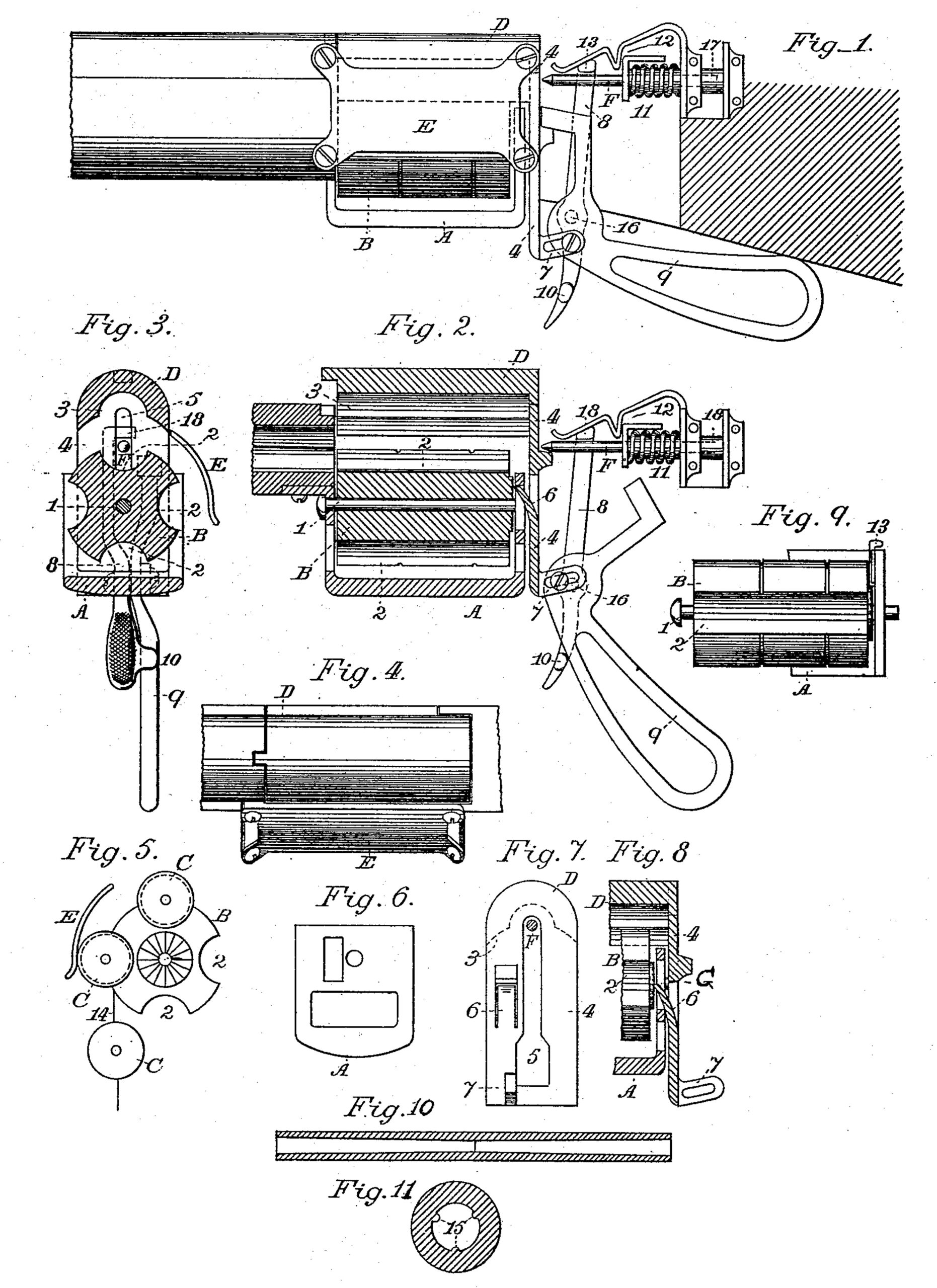
Figure 1 is a longitudinal elevation of my breech-loading fire-arm. Fig. 2 is a longitudinal vertical section through the revolving chamber and actuating mechanism. Fig. 3 is a vertical transverse section through the chamber, breech, and mechanism. Fig. 4 is a plan of the breech and guide-plate. Fig. 5 is the end elevation of chamber and ratchet for turning the chamber; also, showing my method of loading. Fig. 6 is a rear elevation of the guard. Fig. 7 is a rear elevation of the breech-piece. Fig. 8 is a longitudinal vertical section through the breech mechanism. Fig. 9 is a plan view of chamber, showing also the release-pin. Fig. 10 is a longitudinal section of a device for shaping the bore of my shotgun barrel, shown as tapering from both ends toward the middle. Fig. 11 is a transverse section of a device for rifling a rifle-barrel.
The guard A is suitably secured to the barrel and the stock of the gun or revolver, and the revolving chamber B is secured to the guard by means of bolt 1. The chamber is provided with semicircular grooves 2 for the reception of cartridge C. G refers to the ratchet.
D shows the cover suitably connected to guard A, provided on its lower inner face with semicircular grooves 3, When the middle groove, 3, and any groove 2 of the chamber are brought suitably together, they form a cylindrical space for inclosing the cartridge.
For greater convenience in placing the cartridges in position, I have secured to the casing the shield E, which covers up and holds in proper position the second cartridge while the first is in position for firing. In my method of loading it is necessary that the cover D should rise and fall to enable me to bring the cartridge in proper position for firing. For this purpose I have properly secured to cover D a tailor breech piece, 4. This tailor breech piece is provided with a suitable guide-slot, 5, through which the needle F acts on the cartridge. I have also suitably secured to the breech-piece the spring 6, which acts on the ratchet G and operates the revolving chamber. I have also secured to the breech-piece 4 the lug 7, and connected thereto the trigger lever 8 and the actuating-lever 9 by means of a screw-bolt passing through the slot and secured to the actuating-lever, the latter being connected to the trigger-lever 8 by a pivot, 16, the combination being such that the screw bolt and slot act as a stop to the motion of lever 9. Whenever I wish to place the cartridge in position for firing, I force the end of lever 9 downward and press the same against lug 10, thereby forcing the lower section of trigger 8 forward and the upper section of the trigger-lever backward, thereby forcing the spring and guard 11 and the needle or pointed bolt F backward sufficiently for the spring catch 12 to act thereon and fall in position before the spring and guard 11, holding the same in tensile position and ready for striking to explode the cartridge. Whenever the lower section of the trigger is drawn back, then its upper lever moves forward, and elbow 18 raises the spring-catch 12, thereby releasing the spring 11, and the pin or bolt F darts forward, the point of the pin F striking the fulminate in the cartridge and exploding the same. The pin or bolt F is suitably secured to the needle-bolt 17.
In case I desire to turn chamber B to the left for the purpose of unloading my fire-arm, then I push the release-pin 13 between the ratchet G and the spring 6, thus preventing the spring from acting on the ratchet and enabling me to turn the chamber to the left. The effect of turning lever 9 on pivot 16 and depressing the lower end of the same is to slightly raise the tail-piece D to permit a fresh cartridge to be introduced. The cartridges may be connected by wire 14 in any usual manner, or used singly. At the same time that lever 9 is turned down around pivot 16 and raises cover D the part B is revolved to bring a fresh cartridge immediately in the path of the firing-pin by means of spring-pawl 6, and simultaneously a cartridge is put under cover E. This same movement also compresses spring 11, as elsewhere specified. A reverse movement of the actuating lever fires the cartridge, as before explained.
I do not confine myself to the described devices and mechanism for operating and securing the cover D and bolt F, as the same results may be obtained by various other devices.
In Fig. 10 I show a vertical longitudinal section of a shotgun-barrel bored, the bore being wide at both ends and narrowing gradually toward the middle of the barrel. This improvement is for the purpose of crowding the charge gradually toward the middle of the barrel, thereby accumulating the force of the charge when exploded by confining the gases, and by tapering the bore toward the muzzle the charge will scatter over a large surface. I am aware, however, that the bore of a gun has been provided with an abrupt contraction or shoulder at or near its end. Such construction, however, does not provide for the gradual accumulation and compression of gases behind the projectile, its action being more abrupt and attended with danger.
In Fig. 11 I show the means I employ for rifling a barrel. I have leaders 15 projecting within the barrel. The leaders have the usual longitudinal twist, as common in rifles. These leaders are pressed into the ball and guide its longitudinal movement.
Having thus fully described my invention, what I claim, and desire to secure by Letters Patent, is-
1. The cover D, provided with the breech-piece 4, and the shield E, attached to said cover, the revolving chamber provided with semi circular grooves for receiving the cartridges, said revolving chamber having on one end the ratchet G, the spring-pawl connected with the breech-piece and engaging with the ratchet to revolve the chamber simultaneously with raising the cover to allow a cartridge to be introduced, and the pivoted actuating-lever connected by means of a bolt with an elongated slot in the tail-piece, whereby the depression of the same about its pivot raises the cover and revolves the chamber, all combined with means for firing the cartridge, substantially as set forth.
2. In combination with the grooved part B, provided with a ratchet and supported to revolve within guard A, the cover D, provided with the tail-piece 4, having slot 5, spring pawl 6, attached to said tail-piece of the cover, and mechanism for moving the tail-piece to raise the cover to admit a cartridge under the same and for simultaneously moving the pawl, and part B, to bring a previously-introduced cartridge in the path of the firing-pin, substantially as set forth.
3. The combination of the cover D, having a slotted tail-piece, 4, and slotted lug. 7, connected to said tail-piece, the trigger 8, provided with stop 10, secured to the lower end of the trigger and in the path of lever 9, said actuating-lever 9 connected by a pivot to the trigger and by a bolt with the slot in lug 7, a needle and an actuating-spring, 11, substantially as specified, whereby, on the depression of the lever against the slot the needle is retracted and the spring compressed simultaneously with the raising of the cover to admit a fresh cartridge.
4. The combination of the guard A, part B, supported therein to revolve on axis 1, and provided on its end with ratchet G, spring pawl 6, and releasing-pin 13, arranged to be pushed between the ratchet and pawl to hold the latter disengaged while the chamber B may be revolved to the left to unload the gun, substantially as set forth.
5. The combination of guard A, slotted to allow the movement of a spring-pawl, 6, part B, supported to revolve therein on axis 1, cover D, provided with tail-piece 4, having spring-pawl 6, and means for moving the cover, tail-piece, and pawl, substantially as specified.
AUGUST GRETH. [L.S.]
Witnesses:
FERDINAND IMHORST,
ALPHONSO B. SMITH.