
US 413975
UNITED STATES PATENT OFFICE.
JOHN T. SMITH, OF ROCK FALL, CONNECTICUT.
REVOLVER.
SPECIFICATION forming part of Letters Patent No. 418,975, dated October 29, 1889.
Application filed February 25, 1889, Serial No. 301,03l, (No model.)
To all whom it may concern:
Be it known that I, JOHN T. SMITH, of Rock Fall, in the county of Middlesex and State of Connecticut, have invented new Improvements in Revolvers; and I do hereby declare the following, when taken in connection with the accompanying drawings and the letters of reference marked thereon, to be a full, clear, and exact description of the same, and which said drawings constitute part of this specification, and represent, in–
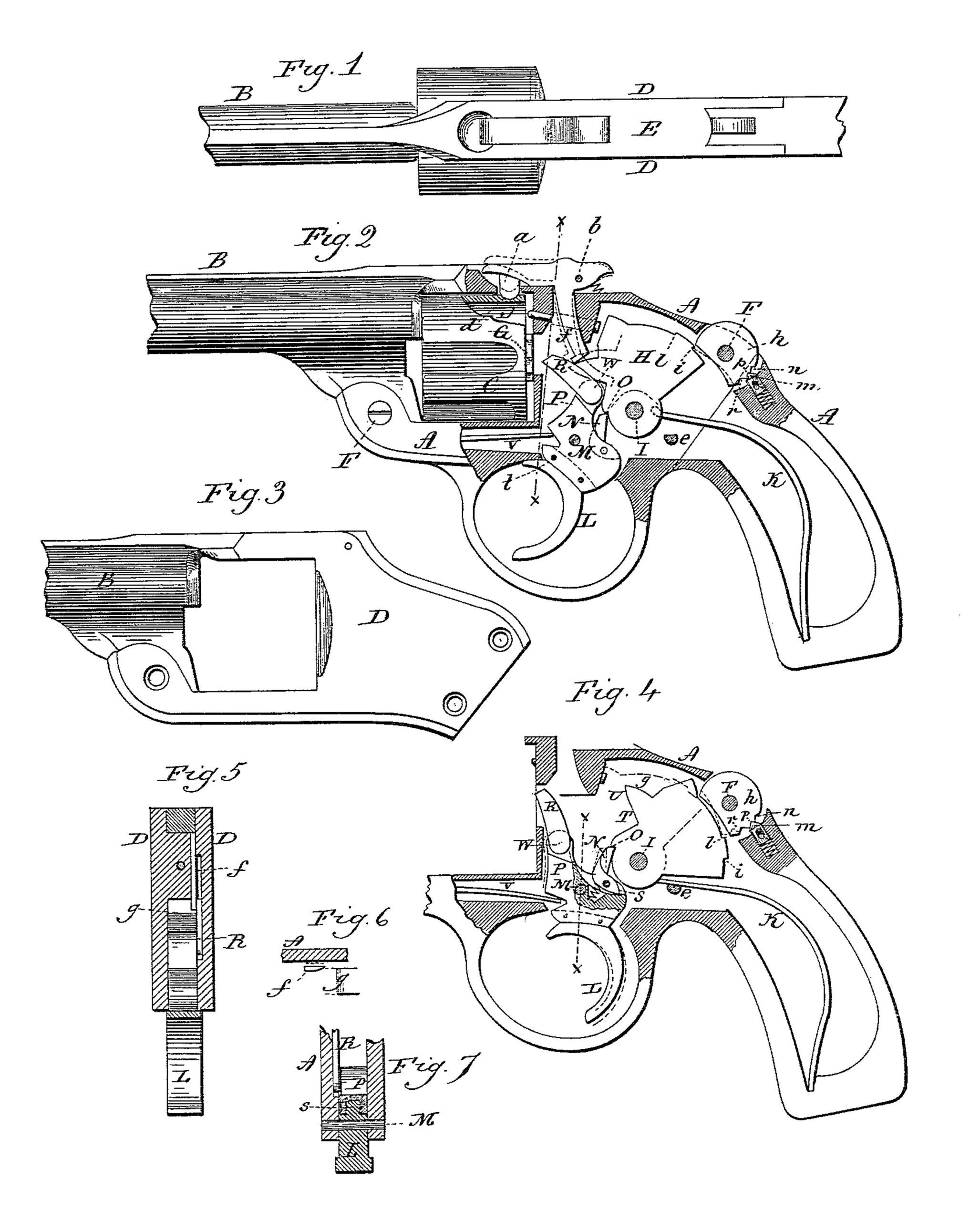
Figure 1, a top view of the revolver; Fig. 2, a side view in partial longitudinal section, showing the operative mechanism in the normal position; Fig. 3, a side view of the barrel and its portion of the frame detached; Fig. 4, the same as Fig. 2, showing the mechanism as with the hammer at the cocked position and about to be discharged; Fig. 5, a transverse section on line x x of Fig. 2, showing the operation of the cylinder-pawl finger; Fig. 6, an under side view of the lower end of the finger, showing the bevel and its operation; Fig. 7, a transverse section through the trigger and frame on line x x of Fig. 4.
This invention relates to an improvement in that class of revolvers in which the hammer is concealed within the frame and cocked and discharged under the pull of the trigger.
The object of the invention is to provide a lock for the hammer in either the cocked or uncocked position as a means of safety; also, to prevent the possibility of the hammer striking the firing-pin, except upon the pull of the trigger; also, to indicate to the person operating the revolver when the hammer has been brought to the full-cock position preparatory to discharge, and to otherwise improve the revolver in details of construction; and the invention consists in the construction as hereinafter described, and particularly recited in the claims.
A represents the part of the frame which forms the handle and the trigger-guard and which carries the lock mechanism.
B represents the barrel, which extends rearward and forms the upper portion of the frame carrying the cylinder C, and forming the two sides D D and top E of the frame at the rear of the cylinder, this barrel portion of the frame being secured to the frame A by screws F F. Said barrel portion of the frame is represented in Fig. 3 detached. The cylinder is hung in the frame in the usual manner, the details of such hanging not shown, being unnecessary to the consideration of the present invention. The cylinder is provided at its rear end with the usual ratchet G.
H represents the hammer, which is hung upon a pivot I in the frame A, and is arranged so as to strike the firing-pin J, which is arranged in the barrel portion of the frame.
K represents the main spring, which is arranged in the frame A and engaged with the hammer in the usual manner.
The trigger L is hung upon a pivot M in the frame A and carries a spring-dog N, which is adapted to engage the cocking-notch O of the hammer, as seen in Fig. 2, and so that a backward pull upon the trigger will, through the dog N, cause the hammer to be turned to the rear and to the cocked position, as seen in Fig. 4. Above the pivot M the trigger is constructed with a projection or arm P, which carries the usual hand or cylinder pawl R hung to the arm, so that, as the trigger is pulled it will engage the ratchet G of the cylinder and turn the cylinder in the usual manner. As the hammer approaches its cocked position, as seen in Fig. 4, the tail S of the pawl N comes to a bearing in its recess in the trigger, as seen in Fig. 4, so that it can no longer turn toward the hammer. Consequently a further pull upon the hammer will force the pawl out of engagement with the notch O of the hammer, as indicated in broken lines, Fig. 4, and permit the hammer to escape, and so escaping the hammer will fly forward under the action of the main spring until it reaches the firing-pin and imparts its blow thereto, which it may do while the trigger is in the rear position, as seen in Fig. 4.
The hammer is constructed with a shoulder T above its hub and upon its forward side, which is in a position to strike the upper end of the projection P of the trigger when the trigger is in its forward position, as seen in Fig. 2, and when the hammer so strikes upon the trigger it cannot reach the firing-pin. Therefore while the parts are in the normal position it is impossible that the hammer can come into contact with the firing-pin. The shoulder T extends forward and forms upon its under surface a cam U. This cam U, when the hammer is down and the trigger in the pulled position, as seen in broken lines, Fig. 4, stands in the path of the top of the projection P, which, as the trigger is returned under the force of its spring V, will act upon the cam U of the hammer and turn the hammer backward to the normal position, as seen in Fig. 2, the trigger thus serving to produce what is commonly called the “rebound” or safety position of the hammer.
In order to complete the rotation of the cylinder before the last part or hammer-releasing portion of the pull of the trigger, the hand R is hung upon its pivot W to the projection P of the trigger in such relation to the pivot M of the trigger that when the trigger has reached its position indicated in Fig. 4, and before the dog N commences its escape from the hammer, the pivot W of the hand R has come into a straight line drawn from the pivot M to the nose of the hand, and this produces the extreme throw of the cylinder, so that the final pull of the trigger, as indicated in broken lines, Fig. 4, will simply carry the pivot of the hand R forward of this line and without effect upon the cylinder. Consequently the cylinder reaches a point of rest in its rotation when the hammer has reached its cocked position and before the discharge of the hammer. When the cylinder reaches the said position of rest, a pawl a, hung in the frame above the cylinder upon a pivot b, engages the notch d in the top of the cylinder, as seen in Fig. 2, thus producing a positive stop of the cylinder, and as usual in revolvers, so that the cylinder may be held in its proper relative position to the barrel, and so as to prevent a possible over-motion of the cylinder under the impulse of its rotation. This engagement of the cylinder and the cessation of the action of the hand R upon the cylinder occurs, as I have stated, when the hammer reaches its extreme position. At the same time the mainspring K is brought to a bearing upon a suitable stop e in the frame, as seen in Fig. 4, this stop being a little distance back from its point of engagement with the hammer. The cessation of the rotation of the cylinder and its engagement, and also the bearing of the mainspring upon the stop e, will be felt by the finger on the trigger sufficiently to indicate to the operator that the hammer has been brought to the cocked position, and that a slight further pull, such as indicated in broken lines, Fig. 4, will release the hammer. This is a convenience in using the revolver, that the operator may first, by the pull of his finger, practically bring the hammer to the full-cocked position, and then when properly set produces the discharge.
To disengage the cylinder-pawl a, it is constructed with a downwardly-projecting finger f from its under side, which is transversely elastic and stands in a position near one side of the forward cam projection on the hammer. The upper surface of this projection on the hammer forms a cam g, and which, when the hammer is in the forward position, as seen in Fig. 2, stands close beneath the lower end of the finger f and as seen in Fig. 5; hence, when the cocking movement of the hammer commences, and before the hand R shall have engaged the ratchet of the cylinder, the cam surface g will strike the corresponding surface of the finger f and force the finger forward, so as to raise the cylinder-pawl, as indicated in broken lines, Fig. 2. The inside of the finger f is beveled, as represented in Fig. 6, and so that as the hammer returns, while the pawl a is in the cocked position, the cam projection of the hammer will strike this inside bevel of the finger f and force it laterally outward, as indicated in broken lines, Fig. 6, until the hammer escapes below the finger; then the finger will return above the projection of the hammer. In the frame and above the hammer a latch h is hung upon a transverse pivot, (here represented as the screw F,) by which the two parts of the frame are secured together, and so that the said latch may be permitted a certain amount of oscillation. The top of the hammer is constructed with two shoulders i l. When the hammer is in its normal position, as seen in Fig. 2, the latch h may be turned down in rear of the shoulder i, as seen in broken lines, Fig. 2, and so as to prevent the turning of the hammer until the latch shall have been thrown out of engagement with the said shoulder i, as shown in Fig. 2. When so disengaged, the hammer may swing backward beneath the said latch h, say, until it has reached its locked position; then the latch h may be turned inward at its rear end and forward of the shoulder l on the hammer, as seen in broken lines, Fig. 4, which will hold the hammer in the cocked position, and it will be held in this position until the latch be thrown out of engagement with the said shoulder l. The back of the latch h is within convenient reach of the thumb of the operator as he grasps the handle, and so that it may be readily turned by that thumb; hence, when the hammer is secured in its cocked position by the latch, as in broken lines, Fig. 4, the trigger being free to return to its forward position, the hammer may be discharged by the slight movement of the thumb required to turn the latch out of engagement with the hammer, so that the latch may serve as a convenient means for discharging the hammer.
To retain the latch h in either of its engaging positions, or in a position to permit the free working of the hammer without engagement with the latch, a spring-stop m is arranged to bear upon the periphery of the latch h, and the adjacent surface of the latch is provided with three notches n p r. The notch n will engage the spring-stop when the latch is turned to hold the hammer at full-cock, as seen in broken lines, Fig. 4. The notch r will in like manner be engaged when the latch is turned to hold the hammer in its down position, as seen in broken lines, Fig. 2, and the intermediate notch p will be engaged by the stop when in its intermediate position, as seen in Fig. 2. The notches are V-shaped, and the nose of the spring-stop is of corresponding shape, so that while the stop will hold the latch in the respective positions it will yield under the rotative force applied to the latch.
It is desirable to make the finger portion of the trigger L of greater width than the width of the mortise of the frame in which the trigger works; but as the trigger-guard is made as an integral part of the frame the trigger cannot be inserted into its mortise from the under side, nor can the finger portion of the trigger, if it be as wide as desirable, be introduced through the upper side of the mortise. To permit such desirable width of the finger portion of the trigger, I construct the trigger in two parts, the upper part P being of a width corresponding to the mortise in the frame, as seen in Fig. 7, and the finger portion L, I make of the desired width. Then to unite the two parts I construct the one part with a tongue s, and the other part with a corresponding groove, as seen in Fig. 7, the tongue of the one part set into the groove of the other part, and pins t introduced transversely through said tongue to secure the two parts together, the broad finger part L being easily introduced from the under side into its place with the other part, and the two parts secured together after such introduction.
While the bearing e, which I have described for the mainspring as the hammer reaches its cocked position, is desirable, it may be omitted, the additional resistance which the trigger naturally meets when the dog N comes to a bearing thereon at the full cocked position being sufficient to indicate to the operator that the cocked position is reached; but I prefer the additional bearing of the spring as a more positive resistance and indicator.
I claim–
1. In a revolver, the combination of the hammer H, hung upon a pivot within the frame, a trigger hung below and forward of the hammer, a spring-dog N, hung in the said trigger and adapted to engage the cocking notch of the hammer, the hammer constructed with a bearing against which the said dog rests as the hammer approaches its full-cocked position, the cylinder-hand R, hung to the trigger forward of said dog and above the pivot of the trigger, the pivot of the hand being in such relation to the pivot of the trigger that when the cylinder reaches its position of rest, under the action of the hand, the hand-pivot will have come into a line drawn from the nose of the pawl to the trigger-pivot, substantially as and for the purpose described.
2. In a revolver, the combination of the hammer H, hung in the frame, a trigger hung forward of and below the hammer, a spring dog N, hung in the trigger and adapted to engage the hammer forward of its pivot, the mainspring K, hung to the hammer, with a stationary bearing e in the frame below the mainspring, and against which bearing the mainspring will strike as the hammer approaches its extreme open position, substantially as described.
3. In a revolver, the combination of the hammer and its operative mechanism arranged in the frame, the back of the hammer constructed with shoulders i l, the latch h, hung upon a pivot in the frame parallel with the axis of the hammer and above the back of the hammer, the forward and rear ends of the said latch, under oscillation, adapted to engage the respective shoulders i l on the back of the hammer as the said hammer is in either its down or cocked position, and a spring-stop arranged to engage the said latch in either of its positions, substantially as described.
4. In a revolver, the combination of the cylinder-pawl a, hung in the frame at the rear of the cylinder, the pawl constructed with a spring-finger f, beveled on its inner rear edge, extending down into the frame and forward of the hammer, the hammer constructed with a cam g, the path of which is in the plane of the said finger f, and so that the said cam will operate upon the finger in its cocking movement, but escape from said finger in the discharge movement, substantially as described.
5. In a revolver, the combination of the hammer H, hung in the frame, the hammer constructed with a projection upon its forward side, forming a shoulder T, and the cam U, forward of said shoulder, the trigger hung forward of and below the hammer, and constructed with an upward projection P, the said projection adapted to engage the said cam and shoulder on the hammer, substantially as and for the purpose described.
6. In a revolver, the frame A, in which the operative mechanism is arranged, a trigger-guard formed as an integral part of said frame, and with a mortise from said trigger guard into the frame to receive the trigger, combined with a trigger composed of a finger-piece L, broader than the said mortise in the frame, and the upper portion of the trigger corresponding to said mortise and hung upon a pivot in the frame, the said finger-piece secured to the said upper portion of the trigger, substantially as described.
JOHN T. SMITH.
Witnesses:
HARRIS WARNER,
SAMUEL. L. WARNER.