
US 402331
UNITED STATES PATENT OFFICE.
MICHAEL KAUFMANN, OF GREENWICH, COUNTY OF KENT, ENGLAND.
REVOLVING FIRE-ARM.
SPECIFICATION forming part of Letters Patent No. 402,331, dated April 30, 1889.
Application filed May 9, 1888, Serial No. 273,305, (No model.) Patented in Belgium November 22, 1887, No. 79,640.
To all whom it may concern:
Be it known that I, MICHAEL KAUFMANN, gentleman, at present residing at 8 Devonshire Road, Greenwich, in the county of Kent, England, have invented new and useful Improvements in Fire-Arms, (for which I have obtained Letters Patent in the following country, namely, Belgium, dated November 22, 1887, No. 79,640,) of which the following is a full, clear, and exact description.
This invention relates to an improved locking device for the barrels of revolving pistols and carbines.
The object of the invention is to provide a locking device whereby the barrel will be securely retained in firing position when discharging heavily-loaded cartridges, and which is easily operated for the purpose of unclosing the breech end of the chambers of the revolver or the barrel of the gun for extracting the spent cartridges and reloading.
Reference is to be had to the accompanying drawings, forming part of this specification, wherein–
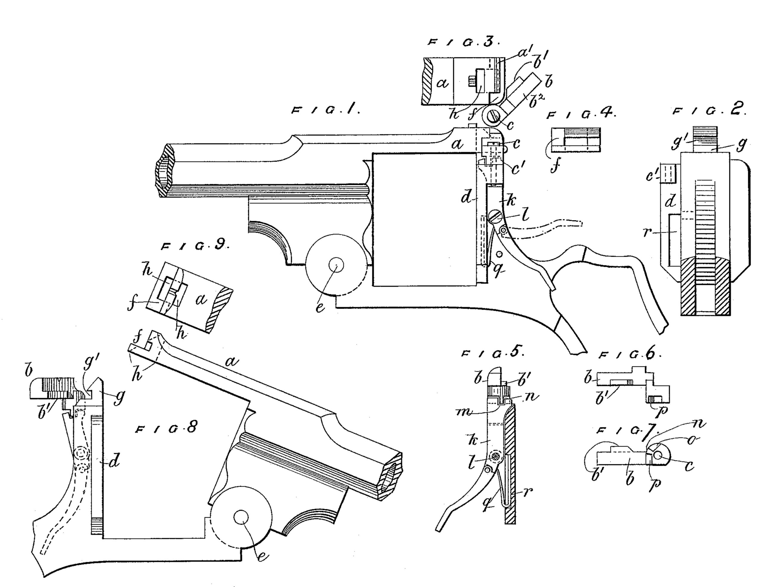
Figure 1 is a side view of part of a revolver, the cylinder being omitted and the locking device being in the locked position. Fig. 2 is a cross-sectional rear view of the frame. Fig. 3 is a top view of the tail-piece or strap of the barrel, the locking device being shown in the open position; and Fig. 4 is an end view thereof. Fig. 5 is a side view of the locking device and the lever by which it is operated, viewed from the opposite side to that shown in Fig. 1, and showing the connection between the lever and locking device. Fig. 6 is a face view of the acting part of the locking device, and Fig. 7 an under side view thereof. Fig. 8 shows the revolver-frame, the barrel being in the tilted position, the locking device being slightly modified and shown in the open position, as viewed from the opposite side to Fig. 1. Fig. 9 is a top view of the tail-piece or strap.
The same letters of reference indicate the same parts in all the figures.
a is the barrel strap or tail-piece, and b the locking-bolt pivoted on a vertical axis, c, at one side of the frame d, the locking-bolt, moving over the top of the frame d in a plane parallel to the longitudinal axis of the barrel when in the firing position, and perpendicular to the plane in which the tail-piece moves when the barrel is tilted on its axis e.
The rear end of the tail-piece a, is notched or rabbeted, as shown at f, and when in the normal position rests upon the top of the frame d, and the locking device b lies in the notch or rabbet f, and so holds the tail-piece securely locked. In order to lock the tail-piece laterally, a central lug, g, formed in one with the frame d, is received in a central aperture, h, made through the end of the tail-piece, and in order to prevent strain on the axis c of the locking device this lug g is notched or undercut at g’ to receive a lug, b’, projecting from the front or inner face of the locking device b, which enters through a corresponding aperture formed in the vertical wall of the rabbet f, so that the locking-bolt b engages both with the tail-piece a and the lug g.
The screw-pin c, on which the locking-bolt b swings, is screwed into a socket or ear, c’, formed on the frame, and the locking-bolt is operated by a thumb-lever, k, pivoted at l on an axis at right angles to the axis c of the locking device, the lever k working alongside of the left-hand lock-plate in position to be readily operated by the thumb of the right hand. The upper end of said lever passes up between the ear c’ and the lock-plate and engages with the boss of the locking-bolt b by notch m in the end of the lever, receiving a heel or lug, n, left or formed by cutting notches o p in the under side of the said boss, in which notches the lugs at either side of the notch in are received. The lug n is situated at a point near the axis c and intermediate thereof and of the locking part of the bolt, so that a slight oscillation of the lever k on its axis will produce a considerable angular motion of the locking-bolt b about its center c. I would observe, however, that the relative positions of the lug n and notch m may be reversed. The lever k is acted on by a strong two-armed spring, q, lodged in a cavity, r, in the frame and bearing against the lever near its pivot, whereby the locking-bolt is normally thrown into position for engagement with the notched lug g and the tail-piece a, if the latter be in its normal position. The end of the tail-piece a moves in an arc of a circle about the center e, and the rear face of the aperture h is inclined tangentially to said arc, as shown in dotted lines in Fig. 8, and is intersected by the rabbet f in the tail-piece in order to permit of the lug b’ of the locking-bolt engaging with the notched lug g, as above mentioned.
In the act of returning the barrel, when tilted, to its normal or locked position, it is not necessary to act on the thumb-lever k for the purpose of throwing back the locking bolt b, as the extreme end of the tail-piece, moving in an arc of a circle, as above mentioned, will meet the front face of the bolt b and force it back, thereby permitting the parts to snap into engagement.
The difference between the two arrangements shown in the drawings is that in Figs. 8 and 9 the end of the tail-piece a has a simple rabbet, f, which is filled up by the locking-bolt b, whereas in Figs. 1 to 6 the rabbet is partly overhung by a lip, a’, formed on the tail-piece, a corresponding recess, b2, being cut in the top of the locking-bolt to receive it; but this lip is entirely inoperative, and, being rounded, merely serves, like the rounded back of the bolt b, to give a smooth finish to the parts. Another slight difference is that whereas in the one case the lug or flange b’ on the locking-bolt is only of a length corresponding to the width of the lug g, in the other it extends to the free end of the bolt b, the vertical face of the rabbet f being undercut to receive it; but neither of these changes in detail in any way affects the locking action.
In revolvers having a removable lock-plate the thumb-lever k may be rule-jointed, in order that it may be turned up, as shown in dotted lines in Fig. 1, for the purpose of permitting the removal of the lock-plate to give access to the lock without dismounting the lever k. The lever k may be dispensed with, the locking-bolt being in that case thrown back by the thumb acting on its free end, in which case it may be preferable to pivot the locking-bolt at the right-hand side.
Having now particular described and ascertained the nature of the said invention and in what manner the same is to be performed, I declare that what I claim is–
1. In a revolving fire-arm, the combination of the supporting-frame having a notched or undercut lug, a tilting barrel provided with a recessed tail-piece or strap fitting over said lug, and a pivoted and laterally-swinging locking-bolt adapted to engage the notched lug and recessed tail-piece, substantially as set forth.
2. In a revolving fire-arm having a tilting barrel provided with a rearwardly-extending tail-piece or strap, the combination, with the rabbeted or grooved and slotted butt-end of the tail-piece, of the notched lug on the frame fitting in the slot of the tail-piece and of the locking-bolt, so pivoted as to move in a plane parallel to the longitudinal axis of the barrel, and perpendicular to the plane in which the barrel moves, said pivoted bolt being adapted to engage in the grooved or rabbeted end of the tail-piece, and to engage at the same time in the notch of the lug on the frame, substantially as specified.
3. In a revolving fire-arm, the combination, with a locking-bolt pivoted on a vertical axis at one side of the frame of the weapon, of a thumb-lever pivoted on an axis at right angles to the axis of the locking-bolt, and engaging at its upper end with said locking-bolt near its axis by a lug on the one received in a notch in the other, as specified, whereby motion of the thumb-lever on its axis will be transmitted to the locking-bolt, in the manner described.
4. In a fire-arm, the combination, with a locking-bolt pivoted on a vertical axis at one side of the frame of the weapon, of a thumb-lever pivoted on an axis at right angles to the axis of the locking-bolt, and engaging there with by a lug and notch for transmitting motion, as described, and of a spring contained in a cavity in the frame and acting on the thumb-lever, as described.
5. In a fire-arm, the combination, with the tail-piece a, having the slot h, and the rabbeted or grooved butt-end f, of the lug g on the frame, having the notch g’, the locking-bolt b, adapted to lie in the groove or rabbet f, and having the lug b’, adapted to engage in the notch g’, the bolt b being pivoted on the axis c at one side of the frame and moving in a plane parallel to the longitudinal axis of the barrel and perpendicular to the plane in which the tail-piece moves, and a thumb-lever, k, engaging with the locking-bolt b by a notch, m, and lug n, and a spring, q, the whole combined for operation, substantially as specified.
The foregoing specification of my improvements in fire-arms signed by me this 17th day of December, 1887.
MICHAEL IKAUFMANN.
Witnesses:
WALTER J. SKERTEN,
GEO. J. B. FRANKLIN.
Both of 17 Gracechurch Street, London, E. C.