
US 395119
UNITED STATES PATENT OFFICE.
HOMER. M. CALDWELL, OF WORCESTER, MASSACHUSETTS, ASSIGNOR TO THE HARRINGTON & RICHARDSON ARMS COMPANY, OF SAME PLACE.
REVOLVER.
SPECIFICATION forming part of Letters Patent No. 395,119, dated December 25, 1888.
Application filed August 18, 1888, Serial No. 288,119, (No model.)
To all whom it may concern:
Be it known that I, HOMER M. CALDWELL, a citizen of the United States, residing at Worcester, in the county of Worcester and State of Massachusetts, have invented certain new and useful Improvements in Fire-Arms, of which the following, together with the accompanying drawings, is a specification sufficiently full, clear, and exact to enable persons skilled in the art to which this invention appertains to make and use the same.
The object of my present invention is to improve the construction of the cylinder-operating hand or pawl and its spring, and the arrangement of the same in combination with the trigger and adjacent mechanism in a manner whereby convenience of manufacture is facilitated and a more perfect and desirable action is produced, while the hand or pawl is prevented from escaping from the cylinder ratchet when the trigger is drawn back or at the moment of disengaging the hammer and discharging the cartridge. These objects I attain by mechanism constructed as shown and described, the particular subject-matter claimed being hereinafter definitely specified.
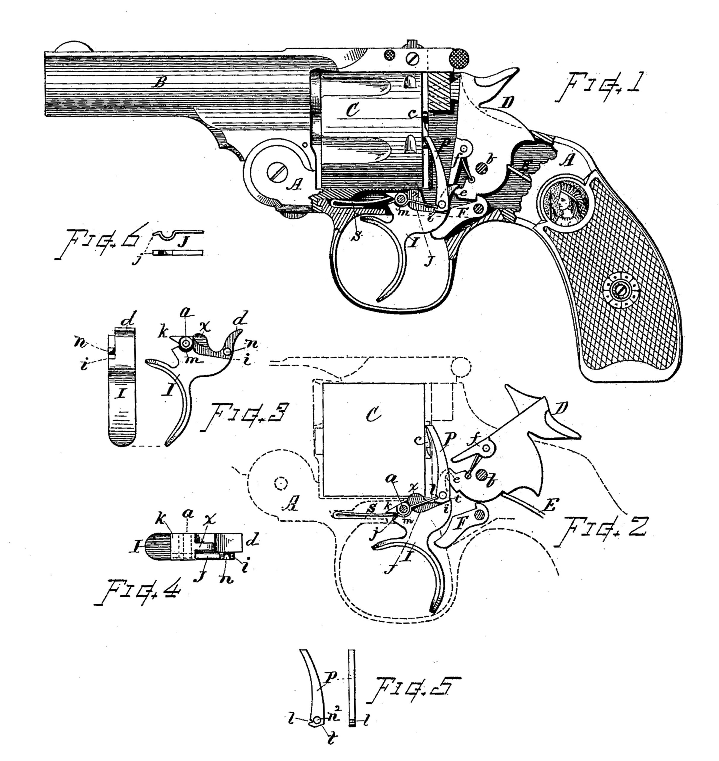
In the drawings, Figure 1 is a side view of a pistol embracing my invention, the frame being broken away to show the action mechanism. Fig. 2 is an outline view showing the mechanism at position as with the hammer thrown back. Fig. 3 shows a side and rear view of the trigger separate from the other parts. Fig. 4 shows a top view of the trigger, Fig. 5 is a side and front view of the hand or pawl separate from the other parts, and Fig. 6 shows a side and top view of the hand spring.
In referring to parts, A denotes the frame, B the barrel, C the cylinder, D the hammer, E the mainspring for throwing down the hammer, and F the rebounding dog, all of which parts may be constructed in well-known manner.
The hammer is pivoted within the frame, as at b, and is arranged for “double action,” it being provided with a fly, f, and a notch, e, as shown; also, for rebound action effected by the rebounding dog F, substantially as heretofore employed in fire-arms of this class.
The trigger I is pivoted in the frame at a, and is provided with the lifting-point d for engaging the fly f and the notch e of the hammer. In accordance with my invention the trigger I is reduced or recessed along its upper part at one side, so as to form a shoulder, as at i, and is provided adjacent thereto with a laterally-projecting pin, n, preferably integral with the body of the trigger, and formed by milling off the surrounding surface when forming the recess, and leaving a sufficient portion of the metal standing to form said pin. A curved slot, m, is formed or cut into the side of the trigger-body concentric with the pivotal axis a for receiving the hand-spring. The trigger also has a forwardly-projecting point, k, for engagement with the spring S, which is arranged, as shown, to press upward thereon and return the trigger to its forward or normal position.
The hand or pawl P, which engages the cylinder-ratchet c for rotating the cylinder C, is made in the form indicated in Fig. 5, it being forwardly curved in its length, and with an opening, n2, in its lower end, whereby it is pivotally supported upon the stud or pin n, externally flush with the side of the trigger. The lower end of said hand is formed with an angular heel or lug, t, which rests upon or engages with the shoulder i when carried to the limit of its upward movement. Said hand is also fitted with a small notch, l, in its front side adjacent to said opening.
The spring J, for pressing the hand P toward the ratchet c, is made in the form shown in Fig. 6, one end being curved so as to fit into the semicircular groove concentric with the trigger-axis a, while its opposite end extends back radially from said axis and engages with the notch l at the front of the hand or pawl in the manner indicated. Said spring is provided with a short end, j, extending forward from the curved portion, which rests on the flat surface at the front of the trigger to prevent the spring from working out of place by the flexure of its rear end.
By recessing the side of the trigger I and arranging the hand P and its spring J thereon in the manner shown the Outer side of the hand comes flush with the side of the trigger, thus bringing it within the inner surface-line of the side frame. This is of considerable advantage in the manufacture, as it avoids cutting a recess for the mechanism in the side of the frame, and also greatly facilitates the assembling of the parts when putting the fire-arm together.
By combining the hand and the spring in the manner indicated I attain the advantage of a quick and easy movement of the hand spring, and also avoid strain upon said spring or pressure by said spring in opposition to the backward movement of the trigger when drawing it back. By means of the hand P and cylinder-stop x, which are both in connection with the trigger, the cylinder is brought to and retained at position with its chamber in proper alignment with the barrel, while the hammer throws forward and discharges the cartridge, and this retention is rendered fixed and positive by means of the lug or angular heel t, which is brought into contact with the shoulder i as the lifting-point d and hand P reach their extreme elevation and at the instant the hammer is released, and by the engagement of the shoulder i and heel t the hand is prevented from swinging back from the ratchet c and releasing the cylinder. Consequently the cylinder is thereby positively held from turning backward until the hammer has completed its stroke.
I am aware that fire-arms have been heretofore constructed in which the cylinder-operating hand is pivoted upon the trigger and combined with a spring for pressing it forward, said spring in some cases being fixed to the frame, while in other cases the spring has been arranged within a drill-hole formed in the trigger, and, again, the spring has been connected with the hand and arranged to press against the frame. These former constructions are, however, so far as I am aware, all different from the particular construction which I herein show and describe, and which constitutes the invention that I desire to cover by my claims; and I hereby disclaim all mechanisms other than such as herein illustrated and described.
What I claim as my invention, and desire to secure by Letters Patent, is–
1. The trigger having its lifting-point d cut away on the side to the shoulder i, with the pivot-stud n, formed integral therewith, in combination with the cylinder-operating hand having an opening that fits over said stud, and the hand-spring disposed in the cut-away space above said shoulder, as set forth.
2. The trigger having the backwardly-curved lifting-point recessed on its side to receive the hand, and carrying the pivot-stud n, formed integrally thereon, in combination with the double-action hammer D, having the fly f and notch e, the cylinder, and cylinder operating hand, as shown and described.
3. The hand or pawl P, having the angular heel t, in combination with the trigger I, carrying the hand pivot-stud n, and having the shoulder or bearing-surface i, that engages said heel, substantially as and for the purpose set forth.
4. In combination, substantially as described, the revolver-cylinder having the ratchet c, the trigger I, having at one side the shoulder i and laterally-projecting stud n, the hand-pawl P, pivoted at its lower end upon said stud, and the hand-spring J, supported in the groove in around the trigger axis and extending radially therefrom with its working end engaging a notch, l, on the front part of the hand, as set forth.
5. The trigger I, having the shoulder i and laterally-projecting stud n, the hand-pawl P, pivoted upon said stud and provided with the angular heel t, adapted to engage said shoulder, and the hand-spring J, supported in a curved groove, m, adjacent to the trigger-axis and extending radially therefrom, with its working end engaging the notch l on the front of the hand, in combination with the frame A, double-action hammer D, and the revolver cylinder having the ratchet c, all substantially as described, and for the purposes set forth.
Witness my hand this 16th day of August, A. D. 1888.
HOMER. M. CALDWELL.
Witnesses:
CHAS. H. BURLEIGH,
ELLA P. BLENUS.