
US 360686
UNITED STATES PATENT OFFICE.
GILBERT H. HARRINGTON AND WILLIAM. A. RICHARDSON, OF WORCESTER, MASSACHUSETTS.
REVOLVER.
SPECIFICATION forming part of Letters Patent No. 360,686, dated April 5, 1887.
Application filed April 7, 1886. Serial No. 198,100. (No model.)
To all whom, it may concern:
Be it known that we, GILBERT H. HARRINGTON and WILLIAM. A. RICHARDSON, both citizens of the United States, residing at Worcester, in the county of Worcester and State of Massachusetts, have invented certain new and useful Improvements in Fire-Arms, of which the following, together with the accompanying drawings, is a specification sufficiently full, clear, and exact to enable persons skilled in art to which this invention appertains to make and use the same.
The object of our present invention is to render fire-arms of the class referred to safer and more convenient for carrying, handling, and use; also, to provide a safety-hammer for fire-arms, particularly applicable to pocket pistols, and especially those known as “double acting,” or in which the “cocking” or raising of the hammer is effected by the trigger mechanism, as well as by drawing the hammer back with the thumb in ordinary manner, and to afford facilities for manipulating said safety hammer without inconvenience, as desired.
Our invention consists in the pistol-hammer of peculiar shape and its arrangement with the frame for operation, as set forth, the hammer being constructed so as to conform in its general outline with the outline of the pistol-frame, and without the usual projection or thumb-piece, the portion of the hammer contiguous to the hammer-seat in the frame being made of such convenient form and properly grooved or checked that the operator can obtain sufficient hold thereon to effect the raising of the hammer when necessary to do so with the thumb, but with no projections that can tend to catch upon the clothing or any extraneous object, and thereby cause an accidental discharge of the fire-arm. The lock frame we also make of such convenient form as facilitates the manipulation of the hammer, such as described, and obviates liability of pinching or injuring the thumb when cocking or letting down the hammer.
The advantages resulting from the construction as herein shown and described are greater safety and convenience in carrying, handling, and use.
The particular subject-matter claimed is hereinafter definitely specified.
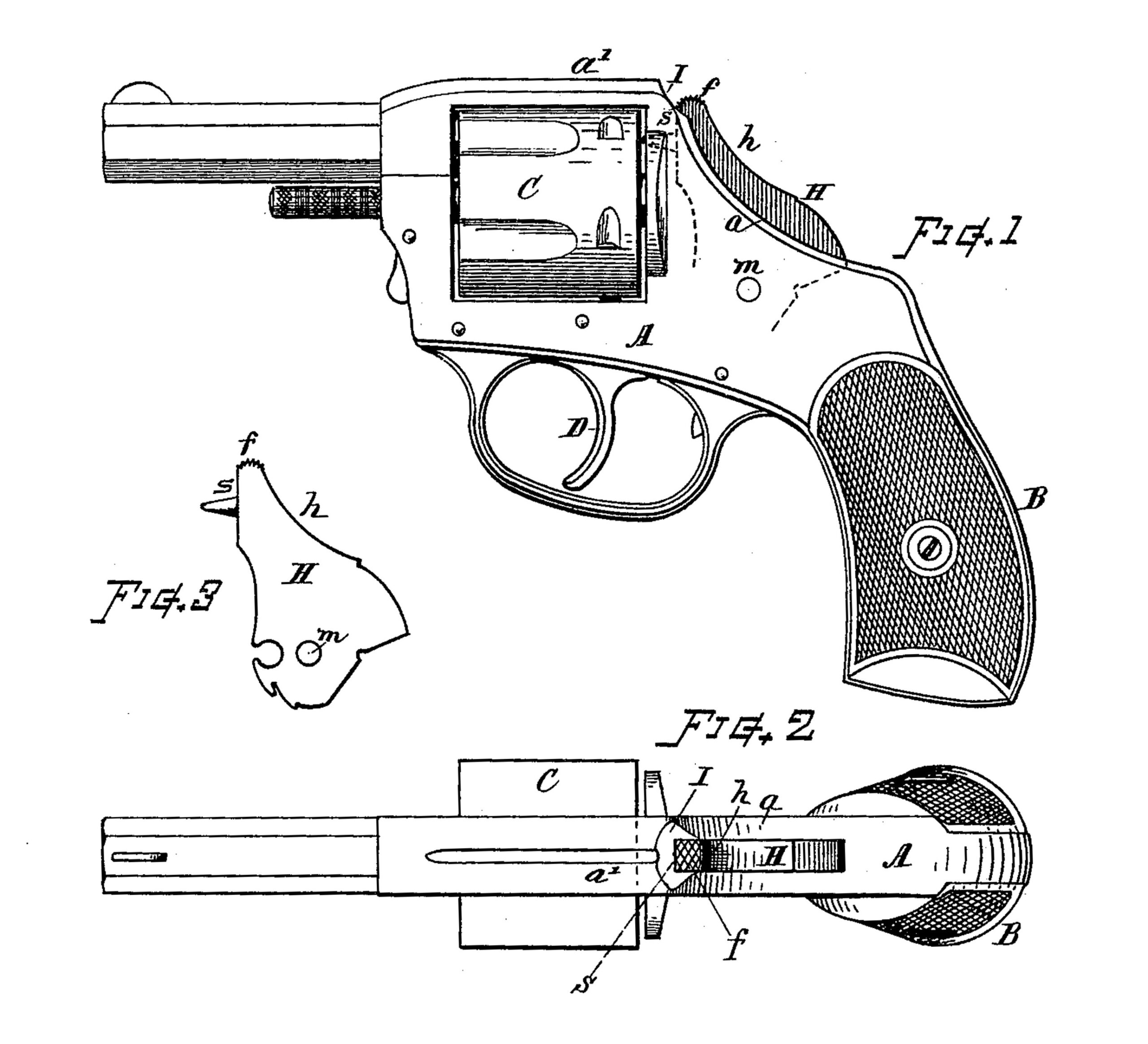
In the drawings, Figure 1 is a side view of a fire-arm having its frame and hammer constructed in accordance with our invention. Fig. 2 is a top view of the same, and Fig. 3 is a side view of the hammer separate from the other parts.
Referring to parts, A denotes the frame of the fire-arm; B, the pistol hilt or handle; C, the cylinder, and D the trigger, which works in connection with lock mechanism of well known or suitable construction, operating on the “double-action’ principle, and which is not herein shown, as its construction is not a feature of the present invention.
The back of the frame A, where it extends upward from the hilt to the top part above the cylinder, is made with a gradually concave curve, as at a, and said curved portion is recessed for the hammer H, which is pivoted in the frame at m, and projects up through this part of the frame, and swings back and forth in its action to and from its striking-seat s at the back of the cylinder in the ordinary manner, when worked by the lock or trigger mechanism.
The upper portion of the hammer, along its back at h, is formed with a concave curve, to substantially conform to the curve of the frame at a, and said hammer is arranged to project So but a short distance out of the frame when it is down, or in normal position with its face resting on the striking-seat s. The top of the hammer terminates in a small rounded end, as at f, which is located at a position below the top line of the upper part, a’, of the frame, and said rounded tip or end f is checked, grooved, or roughened, as indicated, so as to give a good holding-surface on the slight rounded extremity f for the thumb.
The frame A is made with a cutaway or depression, I, at the angle between the curved portion a and the top portion, a’, the metal at that position being formed, as indicated, to meet the rounded end f of the hammer in such manner that the thumb will be warded off from the seat s, so that it will not be pinched between the seat and the face of the hammer when working or letting down the hammer with the thumb on the end f thereof,
In the construction of the several parts of the fire-arm other than those herein specifically defined no novelty is herein claimed, and such parts may therefore be made in any convenient and suitable manner, as preferred.
We are aware that heretofore revolvers have been constructed with hammers having convex backs without the usual thumb projections, and closing on line with the top of the frame, and also with rounded grooved tops projecting above the frame. Such constructions we do not therefore herein claim.
What we claim as of our invention, and desire to secure by Letters Patent, is–
1. In a revolver, the hammer H, made in the shape shown and described, with the back concaved to substantially conform to the outline of the frame A, its upper end terminating below the top line of the frame in a small rounded end, the top surface of which is checked or grooved, the frame being cut away or beveled adjacent to the top of the hammer-striking seat, as and for the purpose herein before set forth.
2. In a revolver capable of self-cocking action, having the frame concaved on its upper side in rear of the cylinder, the hammer H, shaped to conform substantially to the contour of the frame, and having its top end terminating in a small rounded apex, as shown at f, below the sighting-line along the top-level of the frame.
Witness our hands this 6th day of April, A. D. 1886.
GILBERT H. HARRINGTON,
WILLIAM. A. RICHARDSON.
Witnesses:
CHAS. H. BURLEIGH,
HERBERT. P. BARTON.