
US 356387
UNITED STATES PATENT OFFICE.
DANIEL B. WESSON, OF SPRINGFIELD, MASSACHUSETTS.
REVOLVER.
SPECIFICATION forming part of letters Patent No. 356,387, dated January 18, 1887.
Application filed October 25, 1886. Serial No. 217,091. (No model.)
To all whom it may concern:
Be it known that I, DANIEL B. WESSON, a citizen of the United States, residing at Springfield, in the county of Hampden and State of Massachusetts, have invented new and useful Improvements in Fire-Arms, of which the following is a specification. This invention relates to revolving fire-arms, and pertains to improvements in the barrel. catch devices thereof; and the invention consists in the peculiar construction and arrangement of the devices for operating the catch bolt, all as hereinafter fully described, and pointed out in the claim.
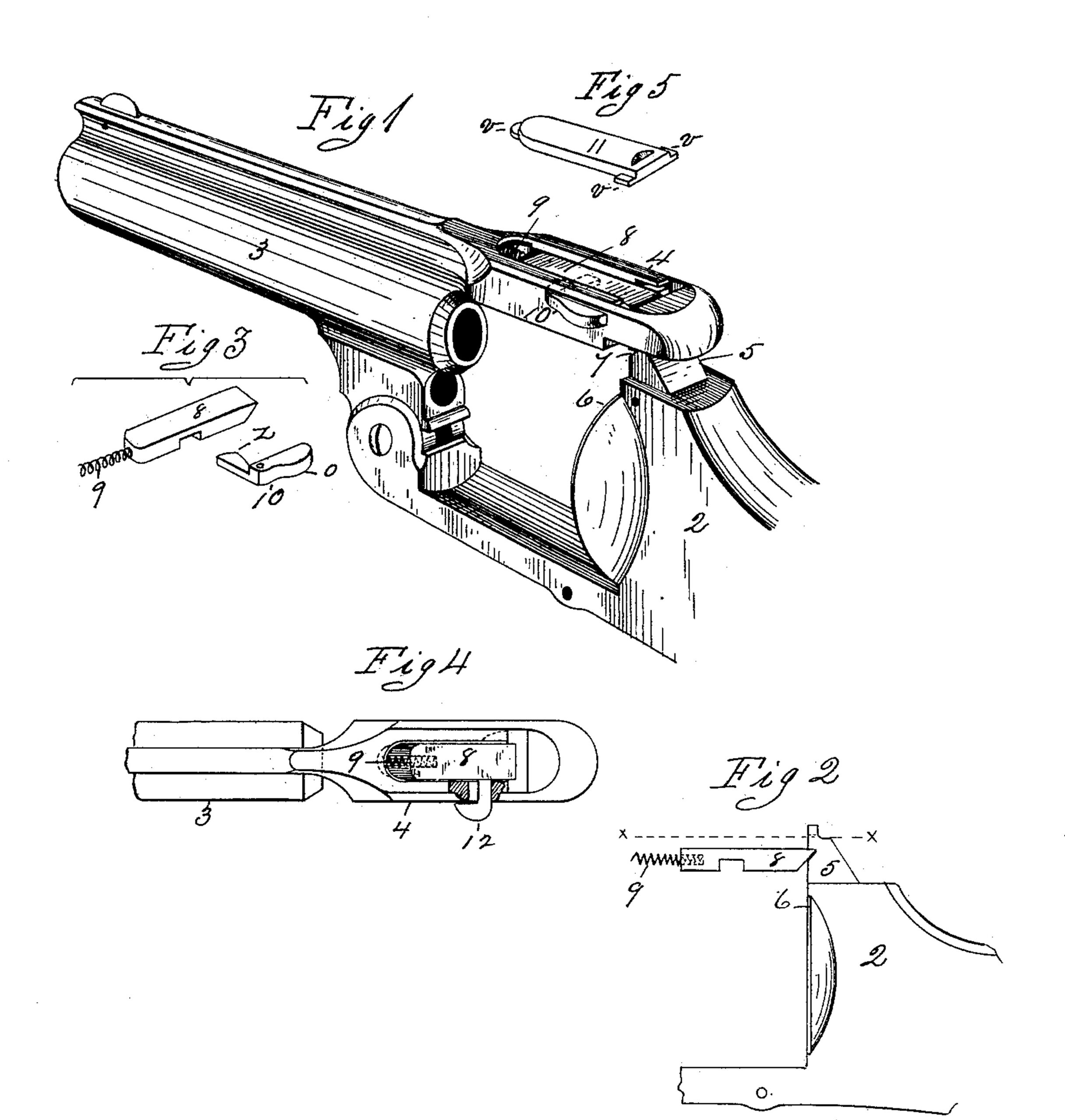
In the drawings forming part of this specification, Figure 1 is a perspective view of the barrel and the adjoining part of the frame of a fire-arm having applied thereto the barrel catch mechanism embodying, my invention, the cover of the chamber in which said mechanism is mainly located being removed. Fig. 2 is a side elevation of a portion of the frame of the arm and of the catch-bolt. Fig. 3 illustrates in perspective views the catch-bolt and spring and an operating-lever therefor. Fig. 4 is a plan view of that portion of the arm to which the barrel-catch is applied, in which one side of the said strap on the rear end of the barrel is shown partly broken away, showing a slightly-modified construction of the catch-bolt. Fig. 5 is a perspective view of the cover of the catch-bolt chamber.
In the drawings, 2 indicates that part of the frame of the arm to which the barrel 3 is hinged in the usual manner, whereby the arm is opened and closed to insert and remove the cylinder thereof, said barrel having the usual rearwardly-projecting strap, 4, on its rear end, which extends over the cylinder of the arm, the rear end of which is provided with a perforation therethrough to receive an upwardly projecting post or arm, 5, on the top of the frame 2, directly over the upper edge of the recoil-plate 6 of the fire-arm, said post being adapted to project slightly above the upper side of the strap 4, as indicated in Fig. 2, in which the dotted line x x indicates the surface-line of said strap, and in the extreme end of the post 5 is formed the usual rear sight notch. The side of the post 5 opposite the end of the barrel has a notch, 7, therein to receive the end of the catch-bolt 8, as shown in Fig. 2. The said strap-extension 4 on the end of the barrel has its outer side chambered to receive therein said catch-bolt 8, as shown, the latter having a sliding motion therein, the form of which bolt is clearly illustrated in Figs. 3 and 4. The end of said bolt which engages with the post 5 on the frame 2 is of chisel shape, and is thereby adapted to be driven rearwardly when the end of post 5 strikes its beveled portion in closing the arm, and the sharp edge which said chisel shape gives to the end of the bolt peculiarly adapts it for absolutely rigid engagement with the upper side of the said notch in the side of the post 5. The rear end of the bolt 8 is perforated to receive one end of a spring, 9, which is located, as shown, between the bolt and the adjoining end of the said chamber, and acts to slide the bolt toward said post 5, and to hold it in engagement with the said notch therein. The under side of the bolt 8 has a transverse groove therein, as shown, in which the arm 2 of an elbow-lever, 10, engages. Said elbow lever, which is clearly shown in Fig. 3, is pivoted in a slot in the edge of the strap 4, (see Fig. 1) and the edge of its second arm, o, projects beyond the edge of said strap. The sides of the said bolt-chamber in the strap 4 and the rear end thereof are grooved to receive the projections v on the edges and end of the cover 11 of said chamber, which is illustrated in Fig. 5. Said cover is adapted to be secured over the catch-bolt in said chamber by placing it in the latter and sliding it endwise, carrying said projections) thereon into said grooves. Said cover 11 fits closely within said chamber and close to the side of the catch-bolt, and holds all of the barrel-catch parts in operative position, and prevents the entrance of any dirt that would hinder the proper operation of the latter.
In Fig. 4 a modified construction of the means for sliding the catch-bolt 8 by the fingers is illustrated, and it consists in extending an arm, 12, from the edge of the bolt through said slot in the edge of the strap 4, instead of using the elbow-lever 10, although the latter is preferable, for reasons below stated.
In operating the fire-arm having my above described improvements applied thereto, it is seen that when the end of the strap 4 is carried over the end of the post 5 on the frame the bolt 8 first recedes slightly, and is then driven in the opposite direction by the spring 9, and its beveled end is carried into the notch in said post, and thereby the end of the strap 4 is so rigidly yoked and fastened to the frame 2 that no strain to which the parts can be subjected by firing the arm can disengage or break said connecting parts.
In handling the arm to open it and remove the cylinder one hand is naturally placed over the barrel, thereby bringing the thumb of that hand on the said projecting edge of the arm o of the elbow-lever 10, and by pressing said arm o the arm z of said lever swings and draws the catch-bolt 8 away from the post 5, thereby permitting the arm to be opened.
In manipulating the bolt 8, when made with the arm 12 thereon, as shown in Fig. 4, the thumb of the operator is pressed against that part of the edge of said arm next to the post 5, and is moved in the direction of the desired movement of the bolt, which thumb action is not quite so convenient or natural as that required to actuate the elbow-lever 10.
What I claim as my invention is–
Barrel-catch mechanism for fire-arms, consisting of a strap extending rearwardly from the end of the barrel to the frame, having a perforation through it near its end, and a chamber therein having a slot through one edge thereof, combined with a catch-bolt located in said chamber and capable of an end wise motion therein, an elbow-lever pivoted in said slot, near one end thereof, having one arm engaging with said catch-bolt and its second arm projecting at the edge of said strap, a spring to move said bolt in one direction, and a post on the frame of the arm entering the perforation in said strap, having a notch in its side to receive the end of said catch-bolt, substantially as set forth.
DANIEL B. WESSON.
Witnesses:
G. M. CHAMBERLAIN,
WM. H. CHAPIN.