
US 339347
UNITED STATES PATENT OFFICE.
REINHARD T. TORKELSON, OF WORCESTER, MASSACHUSETTS, ASSIGNOR TO IVER JOHNSON, OF SAME PLACE.
REVOLVER.
SPECIFICATION forming part of Letters Patent No. 339,347, dated April 6, 1886.
Application filed October 29, 1885. Serial No. 181,242, (No model.)
To all whom it may concern:
Be it known that I, REINHARD T. TORKELSON, of the city and county of Worcester and Commonwealth of Massachusetts, have invented certain new and useful Improvements in Fire-Arms; and I do hereby declare the following to be a full, clear, and exact description of the same, reference being had to the accompanying drawings and letters of reference marked thereon, forming a portion of this specification, and in which–
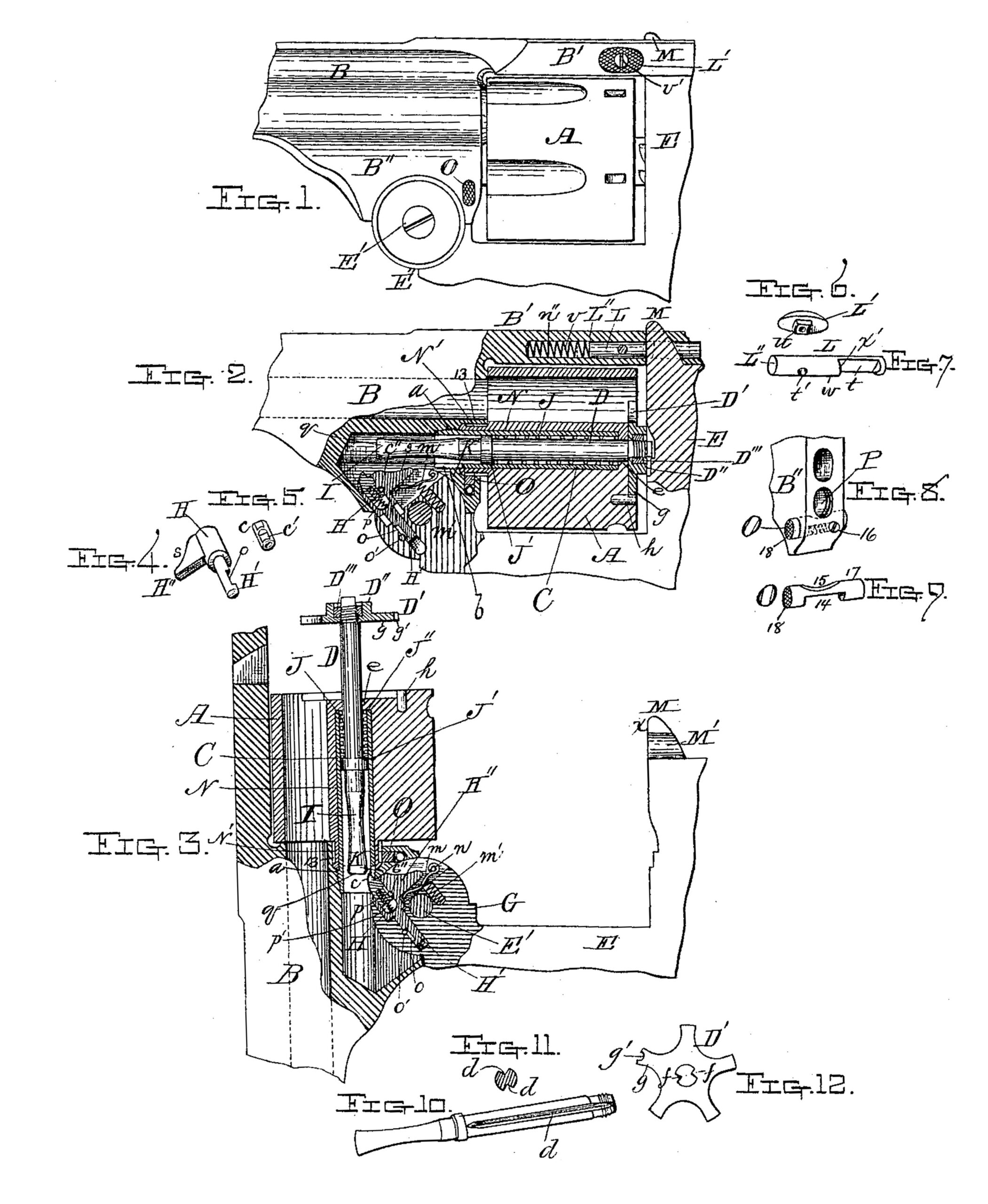
Figure 1 represents a side view of so much of a fire-arm as is necessary to illustrate my present invention, as will be hereinafter more fully described. Fig. 2 represents a longitudinal vertical central section of some of the parts shown in Fig. 1, other parts being represented as broken away. Fig. 3 represents a portion of the parts shown in Fig. 2 when the frame is turned down or back to operate the cartridge-shell ejector, as will be hereinafter more fully described. Figs. 4, 5, 6, 7, 8, 9, 10, 11, and 12 represent parts of the arm more in detail, as will be hereinafter more fully described.
To enable those skilled in the art to make and use my present improvements or invention in fire-arms I will proceed to describe the same more in detail.
In the drawings, the part marked A represents the cylinder; B, the rear part of the barrel which supports the sleeve C, upon which the cylinder turns. Sleeve C is provided with a screw-thread, a, upon its rear end, by which it is secured to the rear lower part of the barrel, as fully indicated in Figs. 2 and 3 of the drawings, and is provided with a slot, b, into which the finger c enters when the cartridge-shell-ejector rod D is thrown forward to eject the cartridge-shells, as indicated in Fig. 3 of the drawings.
E represents a section of the frame pivoted to the barrel at E’, so that it can be turned back from the cylinder, as shown in Fig. 3, and which operation not only exposes the rear part of the cylinder, but also causes the ejector-rod, with its spider D’, to be forced back, thereby ejecting the empty cartridge shells preparatory to the insertion of loaded cartridge-shells. Ejector-rod D is provided in this instance with two grooves, d d, one on each side, as illustrated in Figs. 10 and 11 of the drawings, Fig. 10 representing a perspective view of the rod detached, and Fig. ll a cross-section through the grooved part of the rod.
Grooves d d serve a double purpose–viz., they fit corresponding projections in the part e of the cylinder, and also receive the projections f f of the spider D’, thereby keeping the spider in its proper relative position, as well as the ejector-rod D. Spider D’ is provided with a boss or shoulder, D”, which is cored out to receive the holding-nut D’’’, which is screwed upon the end of ejector-rod D, as fully indicated in Figs. 2 and 3 of the drawings. One projection, g, of spider D’ is provided with a concavity, g’, which fits over one side of the steady-pin h, inserted in the cylinder A, and which, with the projections f f, serve to hold the spider D’ and ejector-rod D securely in position during the use of the arm. The rear under part, E”, is slotted out to receive the tongue or hinge part G, and through which tongue or hinge part the pivot-bolt E’ passes, and within tongue or hinge part G are fitted the devices which operate the ejector-rod D, said devices consisting of the finger c, which in turn is supported in a hole bored in the sliding part H, provided with a notched stem, H, and a projection, H”, and said sliding part H is forced out by the combined action of flat spring m and spiral spring m’, flat spring turning on pivot n, and spiral spring m’ being fitted in a hole formed in tongue-piece G, with one end pressing against the base of flat spring m. By this arrangement a short spiral spring can be used, and yet secure the proper motion of the sliding part H. The stem H’ of the part H is cut away, as seen at o, and in which slotted part a small pin, o’, is fitted, to limit the throw or forward movement of the part H, and thereby prevent its being thrown out of its proper position.
Finger c is provided with a notch, c’, through which passes a small pin, c”, there by keeping the finger c from turning and also from being thrown out of position by means of the spiral spring p, one end of which rests against the bottom of the hole p’ in sliding piece H, while the other end of said spring works in a hole in the bottom of finger c, there by forcing the latter up, as indicated in Figs. 2 and 3 of the drawings. It will be observed that the rear part of ejector-rod D is made in the form of a double cone or concaved part, I.
The operation of the cartridge-shell-ejector devices now described is as follows: When frame part E is turned down, finger c strikes against the end q of the rear part, I, of ejector-rod D and forces it forward, thereby moving spider D’, which in turn, acting upon the flanges of the cartridge-shells, ejects the same, and just before frame E reaches its extent of motion end q slips from the finger c, when ejector-rod D and spider D’ are thrown back into their normal positions by the expansion of spiral spring J, which had been contracted or compressed by the forward motion of ejector-rod D, one end of said spiral spring pressing against shoulder J’ on ejector-rod D, which spring J encircles, while the other end of spring J” presses against the shoulder J of the cylinder A. As frame E is turned back and its tongue G is rotated the cam-surface s of the projection H” of the sliding part H comes in contact with the projection K, thereby gradually forcing sliding part H back until it with draws finger c sufficiently to allow the end q of ejector-rod D to slip over the point of finger c as soon as the cartridge-shells have been ejected, and when the frame is turned back into its normal position, as shown in Fig. 1, finger c is depressed by coming in contact with the concave surface of the part I of ejector rod D, thus allowing the sliding part H and finger c to be returned until they assume the positions shown in Fig. 2. It will be observed that one side of the end of finger c is notched, while the other is rounded off, the notched side coming in contact with the end of ejector-rod D, to eject the cartridge shells, while the curved side comes in contact with the concaved side of the ejector-rod during the back movement of the finger.
By employing the combination of sliding finger c with sliding piece H, springs m and m’, a sufficient motion is obtained for the finger c to strike the end of ejector-rod D when back in position, as shown in Fig. 2, and at the same time give it the necessary throw to eject the cartridge-shells, and that, too, without employing long springs, thus enabling the entire mechanism to be arranged in a compact manner, as fully illustrated by the drawings. A locking-piece, L, is arranged in a hole, n”, bored longitudinally in the rear upper part, B, of the barrel part B, said piece L being provided with a slot, t, and a hole, t’. A slot is also made in the side of the part B’, of sufficient size to permit the projection u on the thumb-piece L’ to pass through, and also have a longitudinal motion back and forth. When the parts are in position, as indicated in Fig. 1, the end L” of locking-piece L bears against the end of spring v, while thumb piece L is fastened thereto by means of screw v’, spring v being compressed when the locking-piece L is arranged in position and the thumb-piece L’ fastened thereto.
The projection M on the frame is provided with a groove, M’, into which the part w of locking-piece L’ is forced by the action of spring v, when the frame is turned up into the position shown in Fig. 1. Groove M’ is a section of a hole a little larger than locking-piece L–that is, the entire hole is just large enough to permit locking-piece L to work back and forth freely in the same, and this hole n” in the top strap, B’, and groove or section of circle M’ inside of projection M on the frame E to receive the locking-piece L, as above stated, is drilled at one operation. This method of manufacture assures a more perfect adaptation of parts, is less expensive, and forms a positive, safe, and desirable locking device.
To unlock the frame the operator presses thumb-piece L’ to the left, so as to bring slot t opposite the groove in the projection M, when the latter can be withdrawn and the frame turned down, and when the frame is turned up again the point x strikes against the shoulder x’ and forces the locking-piece back until groove M comes opposite shoulder x’, when the latter springs into the same and locks the frame, and which locking is automatic. As locking-piece L is inserted in a hole in the rear end of the strap or upper part, B’, against spring v, it is not liable to be clogged, and, besides, the user of the arm can always tell at a glance at the outer end of locking-piece L if the frame is securely locked, and as locking-piece L slides out into a horizontal groove extending entirely, through one side of projection M, any dirt or foreign matter is not liable to lodge or collect in said groove, and the entire locking mechanism can be cheaply constructed and is not liable to become deranged by use.
The tubular part N of cylinder A is provided with a projection or grooved hub part, N’, which extends beyond the end of the cylinder sufficiently far to bring its groove 13 over the cylinder-locking pin O, fitted in the rear lower part, B”, of the barrel part B. The position of cylinder-locking pin O, as well as its peculiar construction, are fully shown in Figs. 8 and 9 of the drawings, said pin being provided with a slot, 14, on one side, having square shoulders, and a concavity, 15, on the other side, and a screw, 16, is screwed into the back of the part B”, the point entering slot 14, while a small spiral spring is arranged between the point of said screw 16 and the other shoulder of stop-pin O, and by its action keeps the large part 17 forced into groove 13 of the hub N’, which enters the hole P in the part B” of the stock; consequently when the cylinder is pushed back in its place the rear end of its hub N’, being beveled, forces locking-pin O to the right, and after passing beyond said pin the spiral spring (shown in dotted lines, Fig. 8) causes said pin to spring to the left, thereby bringing the large circular part 17 into groove 13 of the hub part N’ and locking the cylinder in place, to unlock which the operator has only to press on the end 18 of locking-pin O, and push said pin in until its concave part 15 comes under the hub part N’, when the cylinder is released and can be removed after the frame part E has been unlocked and turned down, as shown in Fig. 3 of the drawings, its locking devices being shown detached in Figs. 6 and 7 of the drawings; and it will be understood that locking-pin L may be arranged to be moved to the right to unlock frame E, if desired.
In Fig. 3 hinged frame-piece E is shown turned back far enough to bring the end of finger c below the end of ejector-rod D, so that spring J can force said rod back into the position shown in Fig. 2.
Having described my improvements in fire arms, what I claim therein as new and of my invention, and desire to secure by Letters Patent, is–
1. The combination, with the top piece or strap which connects the barrel with the frame, and having a spiral spring inserted in a longitudinal hole extending in from the rear end thereof, and the hinged frame provided with the projection M, having a groove, M’, on one side and inline with the barrel, of a notched locking pin or piece, L, inserted from the rear against the spiral spring in the hole in the top piece or strap, B, and provided with a thumb piece, L’, whereby, when the frame is turned up and its projection M passes up through the slot in strap B’, locking-pin L will be forced back by its spring, so that one side of its middle part will enter groove M’ in one side of projection M, thereby locking the parts securely together and bringing its rear end to the end of the longitudinal hole in the strap-piece B’, in full sight of the operator, substantially as and for the purposes set forth.
2. In a revolving fire-arm, the combination, with the rear lower part of the barrel and forward end of the cylinder, provided with a grooved hub for receiving a locking-pin, of a locking-pin inserted in a hole or slot running transversely under the grooved hub of the cylinder, and provided with a recess on its lower side to receive an operating-spring and a stop screw, and with a concavity on its upper side to receive the grooved hub on the cylinder, whereby, when the locking-pin is pressed out by the operating-spring, the cylinder will be locked, but released when the operator pushes locking-pin in, so as to bring its concavity under the grooved hub of the cylinder, substantially as described.
3. In a revolving fire-arm, the combination, with the ejector-rod provided with grooves d d, one on each side, of a cartridge-shell-ejecting spider, D’, provided with a cored boss or shoulder, D”, for receiving nut D’’’, an opening for the passage of the screw end of the ejector-rod, two projections, f f, to fit the grooves in the ejector-rod, and two projections at rear of center hole in cylinder, to also fit the grooves in the ejector-rod, all substantially as described, whereby, when the ejector spider D’ and nut D” are in position upon the ejector-rod, spider D’ will not be liable to wobble or twist out of its relative position when in use.
4. In a fire-arm, the combination of the hinged frame E, ejector-rod D, a sliding part, H, provided with a notched stem, H’, and projection H”, acted upon by flat spring in and spiral spring m’, substantially as shown and described, and for the purposes stated.
5. The combination, with ejector-rod D and hinged-frame part E, of sliding part H, provided with notched stem H’, cam projection H”, finger c, and spring p, arranged in relation to each other, as described, whereby, when the hinged frame E E’ is unlocked and turned down, finger c will come in contact with the end of ejector-rod and force it out until cam projection H” depresses it, thereby releasing ejector-rod, which then returns to its normal position, substantially as described.
6. In a breech-loading fire-arm, the combination, with the hinged frame by which the cylinder is locked in position, said frame being provided with a slotted tongue, G, at its inner end, for both hinging the frame to the rear under side of the barrel and for supporting the devices for forcing out the ejector-rod, the ejector-rod fitted to slide back and forth in the sleeve upon which the cylinder turns, and a stationary projection, K, on the rear under side of the barrel, located above and in rear of the frame-pivot and in the path of the ejector devices, of part H, fitted to slide in the slot in that part of tongue G which extends beyond the frame-pivot, flat spring m, arranged in the slot in the tongue-piece G, with one end pivoted thereto, its free end pressing up against cam projection H” of the slide-piece H, spiral spring m’, fitted in a hole in tongue G, one end resting on the bottom of said hole, the other end pressing up against the flat spring m, and finger c, fitted in a hole in the outer end of sliding piece H, all arranged and combined substantially as described.
REINHARD T. TORKELSON.
Witnesses:
THOS. H. DODGE,
HENRY L. MILLER.