
Britain 6826
AD. 1835 № 6826.
Locks and Breeches of Fire-arms; Combining several Barrels in One Piece of Artillery; and Machinery for Boring Cannon, &c.
DODDS’ SPECIFICATION.
TO ALL TO WHOM THESE PRESENTS SHALL COME, I, Isaac Dobbs, of Hoxley Iron Works, in the Parish of Tipton, in the County of Stafford, Engineer, send greeting.
WHEREAS His present most Excellent Majesty King William the
Fourth, by His Letters Patent under the Great Seal of Great Britain, hearing date at Westminster, the Thirteenth day of April, in the fifth year of His reign, did, for Himself, his heirs and successors, give and grant unto me, the said Isaac Dodds, His espicial license, full power, sole privilege and authority, that I, the said Isaac Dodds, my executors, administrators, and assigns, or such others as I, the said Isaac Dodds, my executors, administrators, and assigns, should at any time agree with, and no others; from time to time and at all times during the term therein expressed, should and lawfully might make, use, exercise, and vend, within England, Wales, and the Town of Berwick upon Tweed, my Invention of “Certain Improvements in the Construction of Fire-arms, Part or Parts of which Improvements may be applied in the Making and Using of Cannon and other Ordnance;” in which said Letters Patent is contained a proviso that I, the said Isaac Dodds, shall cause a particular description of the nature of my said Invention and in what manner the same is to be performed, to be inrolled in His Majesty’s High Court of Chancery within six calendar months next and immediately after the date of the said in part recited Letters Patent, as in and by the same, reference being thereunto had, will more fully and at large appear.
NOW ENOW YE, that in compliance with the said proviso, I, the said Isaac Dodds, do hereby declare that the nature of my said Invention, and the manner in which the same is to be performed, is particularly described and ascertained in and by Drawings particularizing the following explanation thereof:
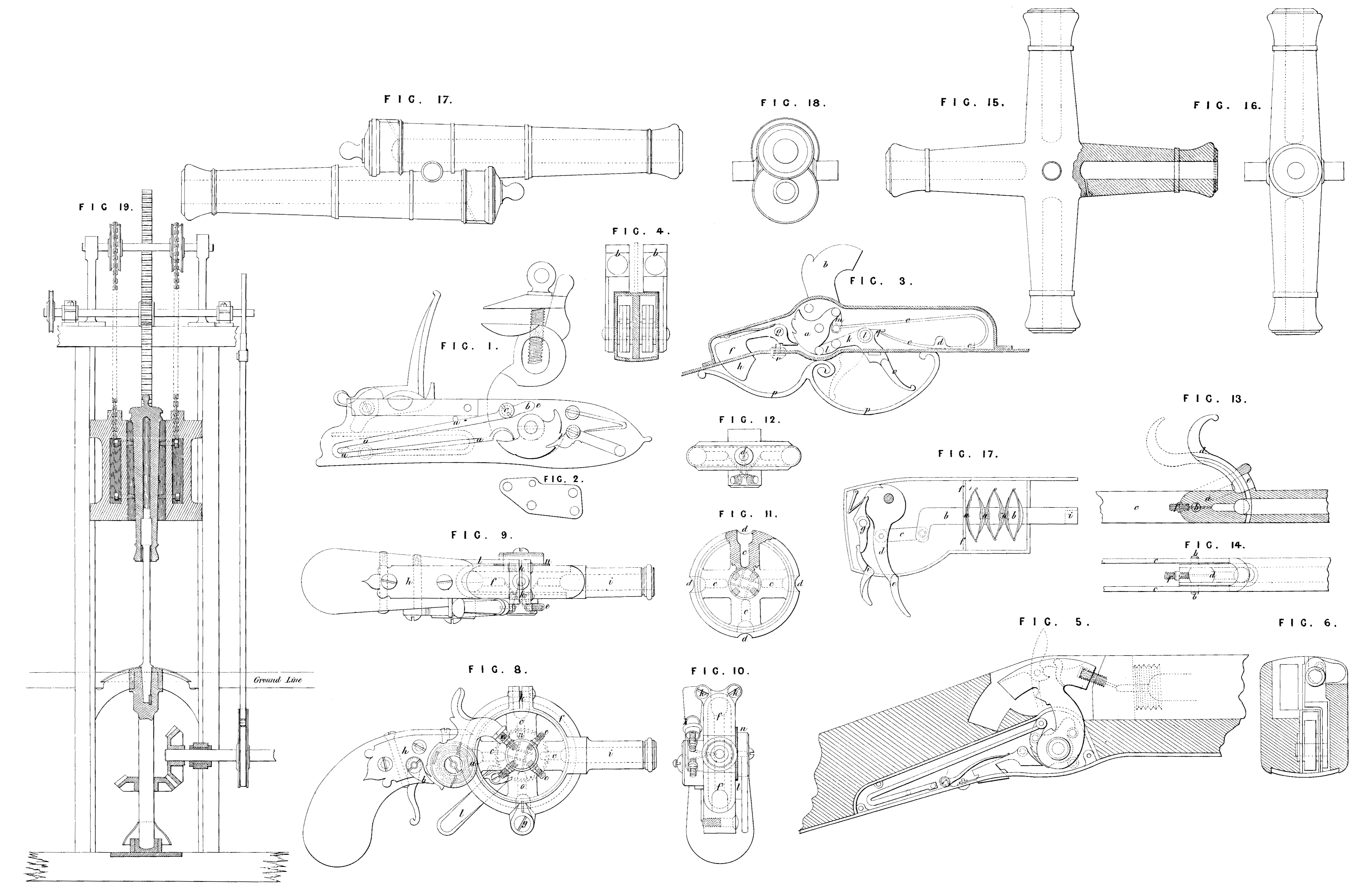
My improvements in the construction of fire-arms apply, firstly, to the locks by which fire-arms are discharged; secondly, to peculiar constructions of the breeches of fire-arms, and modes of loading them; thirdly, in the construction of ordinance with a plurality of barrels; and fourthly, in the arrangements of machinery for boring the internal surfaces of the barrels of fire-arms. In the accompanying Drawing Figure 1, represents the internal construction of a lock for an ordinary musket, in which the main spring has a greater range of clastic action is more powerful and strong, and is so situate as to require a shorter lock plate than those of the usual construction. The spring is formed nearly like an ordinary main spring, a, a, being the tail, as usual, but the affixing or fulcrum end is extended as at b, b, over the tumbler. The screw by which the spring is affixed to the plate is shewn at c; and d, is the stud which constitutes the stop or fulcrum. By this arrangement it will be seen that, in addition to the elasticity of the part a, a, the part b, b, will also be a spring up to the fulcrum or stop d. Figure 2, shews the bridle piece detached, through which the end of the axle of the tumbler works, and it is affixed to the lock plate by the screws of the main spring, the sear, and the sear spring, by which means greater stability is given to the main spring than in the ordinary construction of musket lock; the back end of the spring at e, forms the stop for the tumbler. Figure 8, represents the interior of a gun lock for discharging upon the detonating principle. a, is the tumbler, to the axle of which the cock 3, is attached in the usual way. The main spring is shewn at c, c, as a double armed lever affixed to the lock plate by the screw d, The fulcrum of the longer arm of the spring is a stud at c, let into the lock plate, and the screw d, is the fulcrum of the shorter arm of the spring. The sear f, turns upon a pin g, and is acted upon by a spring behind the under part of the sear at A, constituting the trigger by which the piece is to be discharged. A bell crank lever k, turning upon a pin at i, is connected by a link l, to the lower part of the tumbler a; and the upper part of the tumbler also carries a link m, which is connected to the end of the longer arm of the main spring. The lower part of the hell crank lever is elongated at o, and extends through the guard plate of the lock for the purpose of enabling the lever to be worked by the finger of the sportsman; and a guard p, p, protects the end of the lever and also the. trigger. In cocking the piece the finger is applied to the tail o, of the bell crank lever, which being drawn back into the position shewn by dots, causes the tumbler to be brought round and the longer arm of the main spring to be raised into tension, and by the same movement of the tail o, a small beak q, at the back of the bell crank lever acting upon the end of the shorter arm of the main spring, brings that end of the spring into tension also, the point of the sear f, by the pressure of the sear spring being at the same time forced into one of the notches of the tumbler which confines the lock in the position of half or full cock. The piece being thus half cocked or cocked, the locking bolt r, may be slidden under the point of the sear by the finger, or by the force of a small spring, and whilst in this position the trigger k, cannot be moved, the sear being confined by the bolt », but on sliding back the holt r, which may be readily done by the finger when the piece brought to the shoulder, the sear is released, when by pressing the trigger k, the point of the sear will be withdrawn from the notch in the tumbler, and the force of the main spring then acting upon the tumbler will bring it and the cock down with great force, and cause the end of the cock to strike.the detonating cap placed upon the nipple of the touch hole, by which the piece will be discharged. It must be obvious that the fulcrum or fulcrums of the double arm’d main spring may be placed in other positions besides those pointed out, perhaps with similar advantage. It will also be perceived that the piece may he cocked without employing the hell crank lever and tail piece o, merely by raising. the cock in the ordinary way. Having described the internal arrangements of this construction of lock, I would add, that a plate may be placed over the works parallel to the face plate, for the purpose of enclosing and giving greater stability to the whole, and excluding moisture and dirt from the interior. Figure 4, is a transverse section taken through the two locks of a double barrelled gun constructed upon the principles last described. Here it will be perceived that the boxes which contain the mechanism of the locks are formed by one middle plate and two side plates conjoined to the upper plate guard plate. Figure 5, is a longitudinal section of a fowling piece having a back action lock enclosed within the stock, and Figure 6, is a transverse section of the same. These Figures shew another modification of gun lock, which with the cock arc entirely enclose within the stock of the gun. The lock may be constructed between two parallel plates, as before described, and has my improved arrangement of the sear, trigger, and safety bolt. The upper part of the cock is formed as the segment of a circle, and moves coincident with the top of the tail piece of the breech. A small lever attached to the top of the cock rises by a spring when pressed by the thumb, for the purpose of affording the ready means of drawing the cock back. Figure 7, shows a sectional elevation of a series of eliptical springs, conjoined for the purpose of obtaining sufficient force to discharge a percussion primer. a, a, a, are the springs, connected together by pins; b, b, is a forked frame carrying the springs, the back end of which fork is connected by a link c, to the tumbler lever d. The tail of the tumbler lever extends through the guard plate at l, and which when drawn back compresses the springs against a stop piece f, and thus puts the springs in tension, and the point of the sear g, being forced by a small spring into a notch in the tumbler confines the lock ready to be let off, which is done by drawing the trigger h. The box containing this lock turns up in the stock on pivots in the side plates, for the purpose of introducing the detonating primer into a recess in the end of the plunger at i. Figure 8, is a side view of a pistol on a peculiar construction, the cock of which forms also a tumbler containing a convolute spring within a circular groove, seen at a, part of the face plate of the cock or tumbler being removed for the purpose of shewing part of the spring within; one end of this convolute spring is made fast to the plate of the tumbler or cock, the other end to the plate of the lock. Hence it will be perceived, that by drawing back the cock the spring will be drawn into tension, and the point of the sear b, falling into a notch in the edge of the tumbler will confine the cock until it is let off by the trigger, as in other constructions of locks. Figure 9, is a horizontal view of the pistol seen in the side view at Figure 8, and Figure 10, is a front view of the same. The pistol here represented has four distinct breeches c, c, c, c, each capable of receiving a distinct load of powder and shot; they arc formed as a wheel, with hollow arms and chambers, shewn detached from the pistol at Figures 11, and 12. Apertures in the periphery of the wheel at d, d, d, d, admit the powder and ball for each charge, and the nipples e, e, e, e, respectively receive a detonating cap, each nipple communicating with its own chamber c. The wheel is held in connection with the pistol by a circular slip f, f, which opens and closes upon a hing joint g. The interior of the slip is made hollow, to fit the curved periphery of the wheel. One semicircular portion of the slip f, is made fast to the stock and lock plate h, and the other semicircular portion carries the barrel i. When the wheel is placed within the slip, as shown at Figure 8, the slip is drawn up tight by screws K, K, and by means of those screws the slip will be made to embrace the periphery of the wheel and allow it to turn within the slip with any degree of tightness. The wheel is turned round within the circular slip by means of an arm or lever l, which carries a click m, taking into a ratchet wheel n, affixed to the side of the wheel, and a spring catch must be attached so as to drop into notches in the edge of the wheel, for the purpose of stopping the wheel, in such positions as shall keep the mouths of the loaded chambers when brought round in exact coincidence with the barrel i. The action of the lever may be made to raise the cock, if required, by means of a connecting link or levers, applied in a variety of ways. A modification of this mode of adapting a moveable breech is shewn in horizontal section at Figure 13, and in elevation at Figure 14, in which one loading chamber only is employed. a, is the breech piece for receiving the loading, which piece is mounted upon pivots b, b, in the top and bottom plates c, c. A lever or handle d, on the side affords the means of withdrawing the breech piece from coincidence with the barrel into the position shewn by dots in Figure 13, when the loading may he introduced through the oblique aperture e, and after charging, the breech piece must be brought again into coincidence with the barrel in the position shewn in the Figure. A detonating cap being now placed upon the nipple f, the piece may be discharged by a lock similar to that shewn at Figure 7, or in any other way, cither upon the percussion or flint principle, as may be thought most desirable. In this construction of gun or pistol with moveable breech pieces, I do not intend to confine myself to any particular number of breech pieces, nor to any particular mode of discharging them, as locks of various constructions may be applied; my improvements in cannon consist in combining several barrels together, in order that the loading may be performed with greater facility than in the ordinary construction. Figure 15, is a side view of the barrels of four cannons conjoined at their breeches, and mounted upon pivots or trunnions extending from the centre; Figure 16, is a front view of the same. Two barrels only, combined at their breeches in a similar way, might he made to turn upon trunnions, or as Figure 17, which represents two barrels conjoined; Figure 18, being a front view of the same. The trunnions are here placed some way up the barrels, for the purpose of economising length. By these constructions one barrel may he loaded whilst the other is preparing for firing, which will not only save time but also allow the barrels to cool after firing, before loading again. The barrels may be attached so that their axis shall be coincident, or they may be placed side by side, or one over the other, and they may be so mounted so as to turn upon their trunnions either horizontally or vertically. Figure 19, represents a machine partly in section, intended for the purpose of boring cannon and other fire-arms, in which the gun to be bored is inverted and held in a frame, descending gradually as the metal becomes bored away. The frame is suspended by chains passed over pullies with balance weights, and may descend by its own gravity between guides, or it may be conducted by a rack and pinion moved by machinery from below. The boring bit is erect, and acts upwards within the cylindrical barrel, and there is a shield beneath to prevent the small particles of metal which fell from passing into the working parts of the machinery. This machine may be placed at any oblique angle to the horizon, the object being simply that the turnings or borings may be enabled to descend by their gravity and not obstruct the operation of the boring bit.
In witness whereof, I, the said Isaac Dodds, have hereunto set my hand and seal, the Twenty-ninth-day of October, in the year of our Lord One thousand eight hundred and thirty-five.
ISAAC (L.S) DODDS.
AND BE IT REMEMBERED, that on the Twenty-ninth day of October, in the sixth year of the reign of His Majesty King William the 1Mourth, the said Isaac Dodds came before our said Lord the King, in His Chancery, and acknowledged the instrument aforesaid, and all and every thing therein contained and specified, in form above written. And also the instrument aforesaid was stamped according to the tenor the Statute made in the fifty-fifth year of the reign of His late Majesty King George the Third.
Inrolled the Thirtieth day of October, One thousand eight hundred and thirty-five.