
Britain 8024
A.D. 1839 № 8024
Fire-arms.
STOCKER AND BENTLEY’S SPECIFICATION.
TO ALL TO WHOM THESE PRESENTS SHALL COME, we, George Stocker and Joseph Bentley, both of Birmingham, in the County of Warwick, send greeting.
WHEREAS Her most Excellent Majesty Queen Victoria, by Her Letters Patent under the Great Seal of Great Britain, bearing date at Westminster, the Ninth day of April, and the second year of Her reign, did, for Herself, Her heirs and successors, give and grant unto us, the said George Stocker and Joseph Bentley, our exors, admors, and assigns, Her especial licence, full power, sole privilege and authority, that we, the said George Stocker and Joseph Bentley, our exors, admors, and assigns, and such others as we, the said George Stocker and Joseph Bentley, our exors, admors, and assigns, should at any time agree with, and no others, from time to time and at all times thereafter during the. term of years therein mentioned, should and lawfully might make, use, exercise, and vend, within England, Wales, and the Town of Berwick upon-Tweed, and also in all Her said Majesty’s Colonies and Plantations abroad, our Invention of “Certain Improvements In Guns, Pistols, and other Denominations of Fire-Arms;” in which said Letters Patent there is contained a proviso that we, the said George Stocker and Joseph Bentley, or one of us; shall cause a particular description of our said Invention, and in what manner the same is to be performed, by an instrument in writing under our hands and seals, or under the hand and seal of one, of us, to be inrolled in Mir said Majesty’s High Court of Chancery within six calendar months nest Immediately after the date of the said in part recited Letters Patent,as upon reference thereto will fully appear:
NOW ENOW YE, that in compliance with the said proviso, we, the said George Stocker and Joseph Bentley, do hereby declare the nature of our Invention,and the manner in which the same is to be per-formed, are particularly described and ascertained in and by the following description thereof, reference being had to the Drawings hereunto annexed, and to the figures and letters marked thereon, that is to say:
The nature of our improvements consists, —first, in forming an explosion chamber within the breech or solid break off of fire-arms; second, in certain new combinations of mechanism for the locks of fire-arms; third, in the application of a suitably modified guard to “self-acting revolving” pistols; fourth, in the construction of an improved trigger guard. These four principal heads of our improvements we shall now. proceed to explain in detail, with reference to the illustrative Drawings.
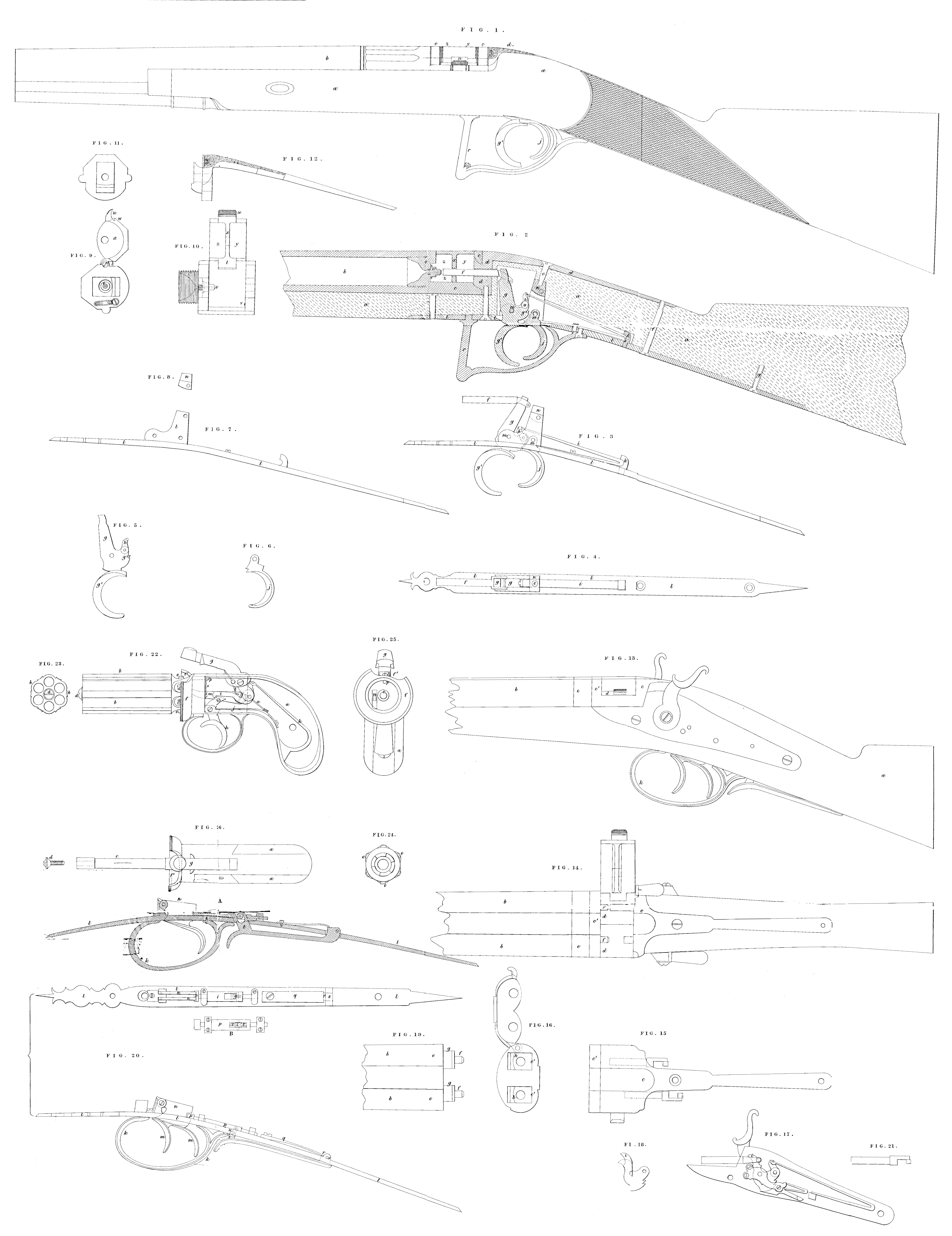
Figure 1, represents an external view of a fowling-piece possessing our aforesaid improvements, a part of the barrel and stock being omitted for want of room. Figure 2, is a longitudinal section of a portion of; the same bringing into view all the novel parts, the principal details of which are separately given in the Figures 3 to 12. Thus, Figure. 3, represents a side view, and Figure 4, a plan of the lock; Figure 5, is the cocking lever; Figure 6, a trigger; Figure 7, a side view of the. lock’ and trigger.plate; Figure 8, is a connecting piece herein-after explained; Figure 9, is an end view, and Figure 10, a plan of. the. breech; Figure 11; is an end view of the break off; and Figure 12, air elevation of the same. [Note: the same letters of reference indicate the same parts wherever they occur.]
At a, is the stock; b, the barrel; and c, the breech screwed thereto; d, is the break off which fits into the breech; e, the nipple screwed into the breech; f, a piston or sticker acting horizontally against the percussion cap in the explosion chamber z; g, the cocking lever, the upper extremity of which is shaped to receive the looped end of the stricker; this cocking lever is shown as uncocked,or as if the gun had just been discharged.
In order to cock it, the piece g is to be pushed forward or towards the muzzle by the thumb, when it takes the position (at full cock) shown at Figure 3. It should also he observed that this cocking lever acts as a tumbler at g². At h, is a swivel lever jointed to the locking lever, and hooked to the main spring i, which thus becomes compressed by cocking, as shewn in Figure 3, and causes it, when liberated by the trigger j, to exert its clastic force (through the medium of the cocking lever) on the stricker f. The lower limb of the main spring i, acts as an ordinary sear spring upon the trigger, as indicated in the Drawing. At k, is a hooked piece provided with a short projecting pin, which enters a hole in the doubled end of the main spring, which is thus prevented from moving upwards or sideways. l, is the lock and trigger plate, (shown separately in Figure 7,) through which there is an opening (as shown in Figures 2, and 4,) to let in the cocking lever and tumbler, which work on pins m, m, that go through them. At n, is a connecting piece, separately shown at Figure 8, which is screwed between the fork of the trigger plate, and has a tapped hole in its upper side for receiving the breech pin o. This breech pin binds the parts of the gun together by screwing the trigger plate l, (which is also the lock plate,) to the break off d, thus making the stock as strong as if the two plates were screwed to it. p, is the guard pin which screws the trigger plate to the break off. q, is the back end pin also connecting the last-mentioned parts together. r, is the guard which incloses the cocking lever and the trigger.
It has already been noticed that a peculiar feature in this improved fire-arm consists in making the breech an explosion chamber. For the more exact illustration of this part, we have given separate Figures 8 the same; Figure 9, representing an end view, and Figure 10, a plan of the breech, showing the lid or cover open, as when the percussion caps are being put on; this lid has a hinge joint at t, and a thumb piece at u, for opening it. When shut down it is held sufficiently fast in its place by a small spring and stud at v, the latter entering a suit-ably formed catch hole w, made in the lid. To the lid is also formed a division plate x, having a hole through it for the horizontal striker to pass, which plate, when the lid is closed, separates the explosion chamber z, from the other part y, of the same cavity.
It will be obvious from the foregoing description, that our explosion chamber may be formed in the break off piece instead of the breech, by sufficiently extending the length of its solid part, an example of which modification of our Invention we shall now proceed to give by reference to Figures 13 to 20, representing the various parts of a double-barrelled gun; whereof Figure 13, is aside view; Figure 14; a plan or view of the upper side of the same with the explosion chamber open; Figure 13, is a separate plan of the break off, only containing the explosion chamber; Figure 16, is an end view of the explosion chamber, with its cover thrown open; Figure 17, is a separate view of the right hand lock; and Figure 18, a plan of the tumbler of that lock, to shew its peculiar form; Figure 19, is a plan of the breech end «of the barrel; Figure 20, are separate views in plan and elevation of our improved guard; and Figure 21, a plan of one of the strikers. The same letters of reference in each Figure indicate the same parts.
At a, is the stock; b, is the barrel; c, the break off; d, the explosion chamber with its cover, which differs in no essential particular from the former, excepting that it is adapted to two barrels, as demonstrated at Figure 16; e, e, the breeches of the two barrels from which project the nipples f, f, by passing through the bridge c’, of the break off the huts g g, of the breeches fitting into the rectangular holes h, h, of the break off. The two locks are of a similar construction to those in common use, excepting that the tumbler is lengthened at that part marked ¢, for the purpose of moving the striker, to accomodate which action the lock plate is made rather wider than usual, as represented.
It will be obvious that the explosion chamber may be made in the break off of a single gun as well as in the breech of a double gun. The peculiarity in our improved trigger guard consists in a new combination of parts, by which the triggers are always kept bolted, except when in the act of discharging, at which time the grasp of the fingers withdraws the bolt. At k, is the bow connected to the trigger plate l; m, m, are the triggers; n, n, the trigger blades, having notches to receive the end of the bolt p, which is forced into it by the pressure of a spring q, acting on the extremity r, of a lever near its fulcrum s, the other extremity of this lever having a stud at ¢ to which the bolt is linked by a swivel joint. By this arrangement it will be obvious that the bolt is withdrawn by the pressure of the hand. A, is i longitudinal section of another improved trigger guard; and B, a plan of the same; k, is the bow; l, l, l, the trigger plate; n, one of the trigger blades; p the bolt shooting into the notch of the trigger blades; in this bolt there is a roller z, and the stud t, is forked above the prongs, being inclined, so that when the lever is raised by the grasp of the hand the prongs run against the roller and draw hack the bolt.
We now proceed to the description of the third head of our improvements, which relates to the self-acting revolving pistol. In these the several barrels, together with the respective nipples and percussion caps, are successively brought under the operation of the hammer, and there by discharged by the mere act of pulling the trigger after each discharge. Pistols of this kind, though exceedingly effective in their action, were prior to our improvement extremely dangerous to the user, owing to their being unprovided with any defence against their accidental explosion, which might be caused by putting them down incautiously upon a table, or, when carried in the pocket, by collision against any hard substance. The safety guard which we have provided for these pistols is of a similar nature to those which have been applied to pistols of a different kind, but by a suitable modification of their construction we have adapted them to the “self-acting revolving pistol, and thus superadded to the improved mechanism of the latter the utmost safety against accidental explosion.
Figures 22, to 26, are illustrative of this improvement; Figure 22, being a side view of the improved fire-arm, with a portion of the stock and side piece removed to show the internal construction; Figure 23, is an end view of a sextuple barrel; Figure 24, is a plan or end view of the breach end of the barrel showing the ratchet movement; Figure 25,is an end view of the entire pistol, excepting the barrel, in order to show the recess for the ratchet; and the extremity of the pall passing through a slot to limit the successive action upon-the ratchet to a single tooth at a time; Fig. 26, is a plan or upper view of the pistol, but having the barrel removed to show the pin that passes longitudinally through its centre; and by its agency fixing the barrel to the body: The same letters in each of these Figures also indicate the same parts. a, is the stock, which is in two parts, and fastened on with a screw that, passes through both sides; b, is the sextuple barrel, which is fastened as before noticed to the body by means of the centre pin c, and a screw d; at the extremity thereof; e, e, e, e, are the nipples which are fixed in cavities hollowed out to receive them in the breech end of the barrel; f represents our improved guard suitably formed on its upper side at f’, to admit the putting on of the percussion caps with great facility, and without raising the hammer for that purpose.
The other parts of the pistol are similar to those which are in common use, therefore we need only briefly refer to them; thus, g, is the hammer operated upon by the trigger A, and intermediate lever; j, is the trigger spring; k, the main spring; and l, is the spring which acts upon the lever i; m, is a paul lever which is forced into a notch between the teeth of the ratchet by means of a spring n, at each successive movement of the trigger; o, is a spring which acts upon a pin p, to give a little friction upon the barrel to keep its motion steady as it turns round by pulling the trigger.
We desire it to be distinctly understood that what we lain as our 2 Invention in the foregoing description are the following:— First, the construction of our explosion chamber, either within the breach, or within the break off of fire arms, however the same may be modified. Second, the combination of mechanism which constitutes the lock represented in the Drawings as attached to the single gun, and that peculiar modification of the. tumbler of the common lock (shown at Figure 18) by which it is rendered applicable to guns provided with our explosion chambers. Third, as regards the new safety bolting guard to the triggers described, and as shown at Figure 20, and Figures A and B, we claim the new combination of mechanism described under letters q, r, s, t, u, and z. Fourth, in the application of the rim guard described to self-acting revolving pistols.
In witness whereof, we, the said George Stocker and Joseph Bentley, have hereunto set our hands and seals, this Seventh day of October, One thousand eight hundred and thirty-nine.
GEORGE (L.S.) STOCKER.
JOSEPH (L.S.) BENTLEY.
AND BE IT REMEMBERED, that on the Eighth day of October, in the year of our Lord 1839, the aforesaid George Stocker and Joseph Bentley came before our said Lady the Queen, in Her Chancery, and acknowledged the Specification aforesaid, and all and every thing therein contained and specified, in form above written. And also the Specification aforesaid was stamped according to the tenor of the Statute made for that purpose.
Inrolled the Ninth day of October, in the year of our Lord One thousand eight hundred and thirty-nine.