
Britain 16638
№ 16,638 A.D. 1888
Date of Application, 16th Nov., 1888
Complete Specification Lett, 16th Aug., 1889— Accepted, 28th Sept., 1889
PROVISIONAL SPECIFICATION.
I, John Carter, of Bracebridge Street, Birmingham, in the County of Warwick Action filer, do hereby declare the nature of this invention to he as follows:—
My Invention relates to revolving firearms which have the lock or firing mechanism known as Webley’s Pistol Mark I, or that known as the Government pattern Enfield Revolver, or similar systems, und the object of the invention is to prevent the discharge of the loaded revolver by the hammer being accidentally knocked down when in the rebounded position.
In “Webley’s” I have a lump projecting upon the inside of the lever or pawl that rotates the cylinder over the front end of the auxiliary main-spring that rebounds the hammer.
In the “Enfield” have a sear pivoted to the lower part of the body, the top part of the sear rests in a bent and along the lower part of the hammer, the lower part of the sear working inside the guard to rest upon the rear side of the trigger when the trigger is pulled back so that the hammer is perfectly free to strike the cartridge.
Dated this Sixteenth day of November 1888.
For the Applicant,
W. E. GEDGE,
Agent.
COMPLETE SPECIFICATION.
Improvements in Revolving Fire Arms.
I, John Carter, of Bracebridge Street, Birmingham, in the County of Warwick, Action Filer, do hereby declare the nature of this Invention and in what manner the same is to be performed, to be particularly described and ascertained in and by the following statement:—
My Invention relates to revolving Fire arms which have the lock or firing mechanism known as “Webley’s” pistol mark I, or that known as the Government Pattern Enfield Revolver, or similar systems, and the object of the Invention is to prevent the discharge of the loaded revolver by the hammer being accidentally knocked down when in the rebounded position.
In “Webley’s” I have a lump projecting upon the inside of the lever or pawl that rotates the cylinder over the front end of the auxiliary that rebounds the hammer.
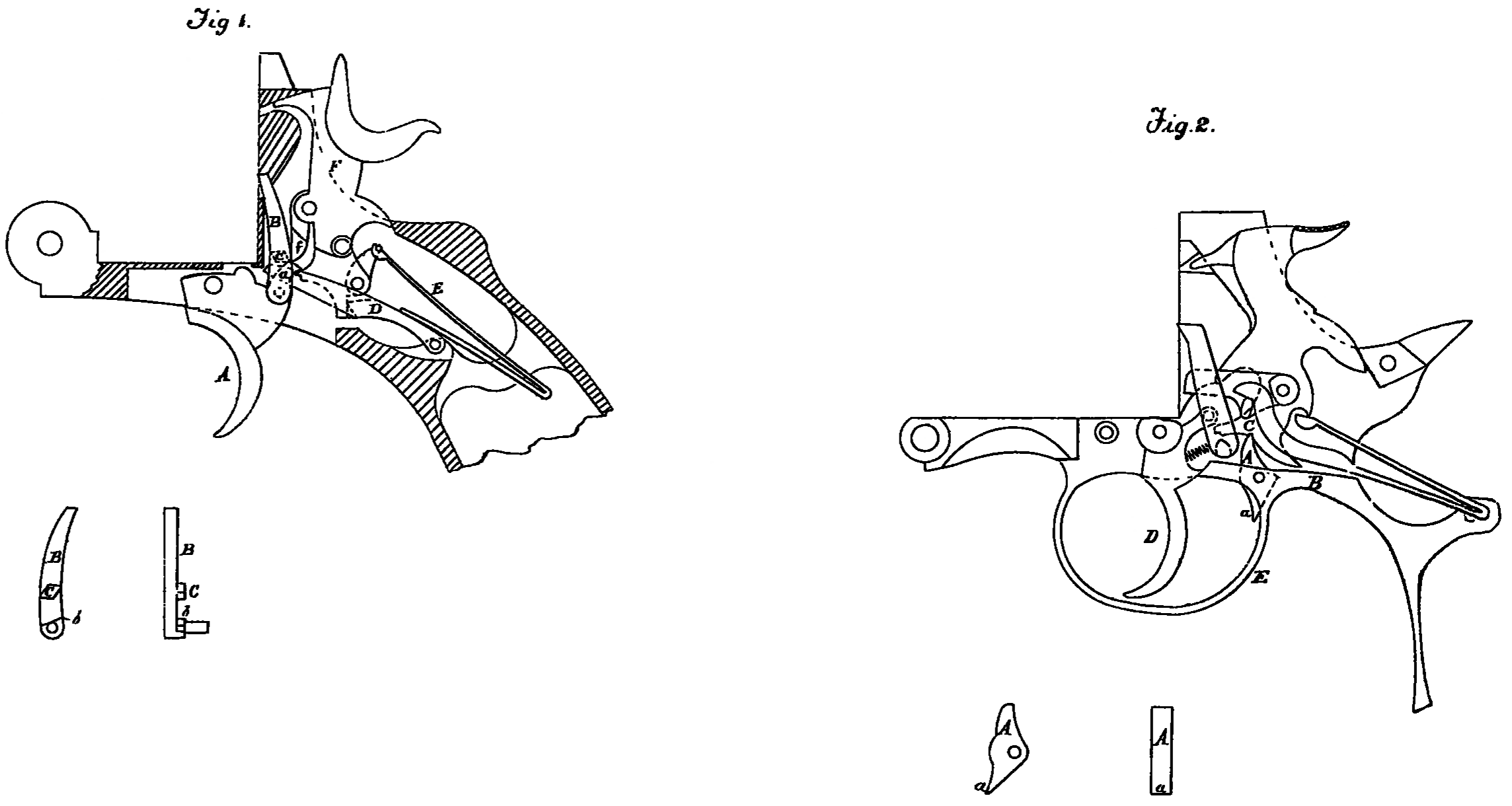
On the accompanying Sheet of Drawing :—
Figure 1 represents in section a “Webley’s” pistol mark I embodying my invention; the hammer being in the rebounded position.
A Being the trigger— a is the sear nose on same.
B Is the level or pawl— b ledge on same.
C The lump or safety block on inside of lever or pawl B.
D Auxiliary.
E Mainspring.
F The hammer— f Hammer catch.
It will be seen that the auxiliary D is between the lump C and the ledge b on the pawl B whereby the sear nose a being under the Hammer catch f the hammer cannot be brought down to discharge the revolver until it is raised for firing.
In the “Enfield” I have a sear pivoted to the lower part of the body, the top part of the sear rests in a bent, and along the lower part of the hammer, the lower part of the sear working inside the guard to rest upon the rear side of the trigger when the trigger is pulled back so that the Hammer is perfectly free to strike the Cartridge.
Figure 2. represents in section an “Enfield” pistol embodying my Invention; the hammer being locked on the rebounded position.
A Is the sear block— a lower part of same-passing through the trigger guard.
B The body upon which-the sear is pivoted.
C Bent on lower part of hammer.
D The Trigger.
E The Trigger guard.
The sear lock A being in the bent C prevents any forward movement of the hammer, which cannot therefore be accidentally knocked down, but on pulling the, trigger D until it meets the part a of the sear block A this latter pivots und leaves the hammer free to strike the cartridge.
I may apply this method of locking the hammer to the “Webley” revolver and to other systems to which I may find it applicable.
Having now particularly described and ascertained the nature of my said Invention, and in what manner the same is to be performed; I declare that what I claim is:—
1. The method hereinbefore described and illustrated Figure l of the accompanying Drawing for preventing the discharge of a loaded revolver by the hammer being accidentally knocked down when in the rebounded position.
2. In a revolving fire arm the lump-or safety-block C on the pawl B substantially as described: with reference to Figure 1 of the Drawing for the purpose specified.
3. The method hereinbefore described and illustrated Figure 2 of the Drawing for preventing the discharge of no loaded. revolver by the hammer being accidentally nocked down when in the rebounded position.
4. In a revolving fire arm the sear block A arranged to operate substantially as hereinbefore described with reference to Figure 2 of the accompanying Drawing for the purpose specified.
Dated this Sixteenth day of August 1889.
For the Applicant,
W. E. GEDGE,
Agent.