
Britain 3427
№ 3427 A.D. 1891
Date of Application, 25th Feb., 1891
Complete Specification Left, 9th Nov., 1891— Accepted, 5th Dec., 1891
PROVISIONAL SPECIFICATION.
Improvements in Revolver Firearms.
I, William John Whiting of 153, Linwood Road, Handsworth, in the County of Stafford, Foreman of Works, do hereby declare the nature of this invention to be as follows:—
My invention relates to improvements in mechanism for holding and releasing the cylinders of revolving firearms of those types which open on a hinged joint for loading and extracting.
The objects of the improvements are, (1) to securely hold the cylinder during the action of the extractor; (2) to allow free rotation of the cylinder when shooting; and (3) to enable the user to easily dismount the cylinder from the axis and remount it on the same when required.
These requirements are fulfilled as follows:—
The cylinder is mounted on a plain axis, which is firmly fixed into the lump of the barrel. A shoulder inside the cylinder abuts against the rear end of this axis to prevent the undue forward movement of the cylinder; and its backward movement is prevented by a teat which comes nearly into contact with the standing breech when the arm is closed. The cylinder is not otherwise fastened to the axis.
On the, front, end of the cylinder is a short tubular projection or sleeve surrounding the axis; and around this sleeve a groove is cut for the purposes hereinafter described, namely the holding and releasing of the cylinder as required.
On the lump of the barrel a lever is pivoted and this lever has a claw to gear into the groove in the sleeve piece on the front end of the cylinder.
This claw, when in gear with the groove, holds the cylinder on its axis against any longitudinal movement, and, when withdrawn from the groove, allows such movement.
The engagement and disengagement of this claw of the lever are effected in one or other of the following ways.
The lever may be actuated by a spring, pressing the lever so as to cause the claw to gear with the groove in the sleeve piece of the cylinder, and the claw withdrawn by the action of a cam on the joint of the body.
In this case the cam acts as follows.
When the arm is closed the cam presses the lever against the spring and draws the claw of the lever free from the groove in the sleeve piece of the cylinder. The cylinder is thus free to revolve for shooting without any drag from the claw.
On opening the arm the cam presses the lever into gear with the cylinder during the action of the extractor, and so secures the holding of the cylinder on its axis even if the spring should fail to act.
After extraction, and while the arm is open, the lever may be pressed out of gear by hand and the cylinder slid off its axis.
This method of construction may be varied by forming a cam on the lever itself and acting on this cam by a stud on the joint: the cam being so shaped as to hold the lever out of gear when the arm is closed; in gear when the extractor is acting; and leave it in gear when the arm is open, but free to be released by hand when the cylinder is to he withdrawn from the axis.
The spring may be dispensed with and all the three, necessary actions of the lever for holding and releasing the cylinder may be effected by the following means.
A cam may be formed on the lever and acted upon by a stud on the joint. The curves of the cam must be such as to cause the lever to engage with or disengage from the sleeve piece of the cylinder as required.
A cam may be formed on, or fixed to the joint of the body and act upon the lever as, the arm is opened and closed to hold and release the cylinder as required.
Or the lever may have a cam, and a supplementary lever, pivoted on the body joint, may act on this cam.
In all cases it is necessary that the freeing of the claw of the lever from the groove in the sleeve-piece of the cylinder when the arm is closed shall be positive and automatic; that the engagement of the claw in the groove, during the action of the, extractor shall also-be positive and automatic; and that, when the arm is fully open, the claw must be in wear with the groove to hold the cylinder in place, but free to be disengaged by hand when it is required to dismount the cylinder from its axis.
Dated this 24th day of February 1891.
WILLIAM JOHN WHITING.
COMPLETE SPECIFICATION.
Improvements in Revolver Firearms.
I, William John Whiting, of 153, Linwood Road, Handsworth, in the County of Stafford, Foreman’ of Works, do hereby declare the nature of this invention and in what manner the same-is to be performed, to be particularly described and ascertained in and. by the following statement:—
My invention relates to improvements in mechanism for holding and releasing the cylinders of revolving firearms of those types which open on a hinged joint for loading and extracting.
The objects of the improvements are:— (1) To securely hold the cylinder during the action of the extractor. (2) To allow free rotation of the cylinder when shooting. (3) To enable the user to easily dismount the cylinder from the axis and remount it on, the same when required.
The following description and -the accompanying drawings will sufficiently explain my invention and how the same is to be performed.
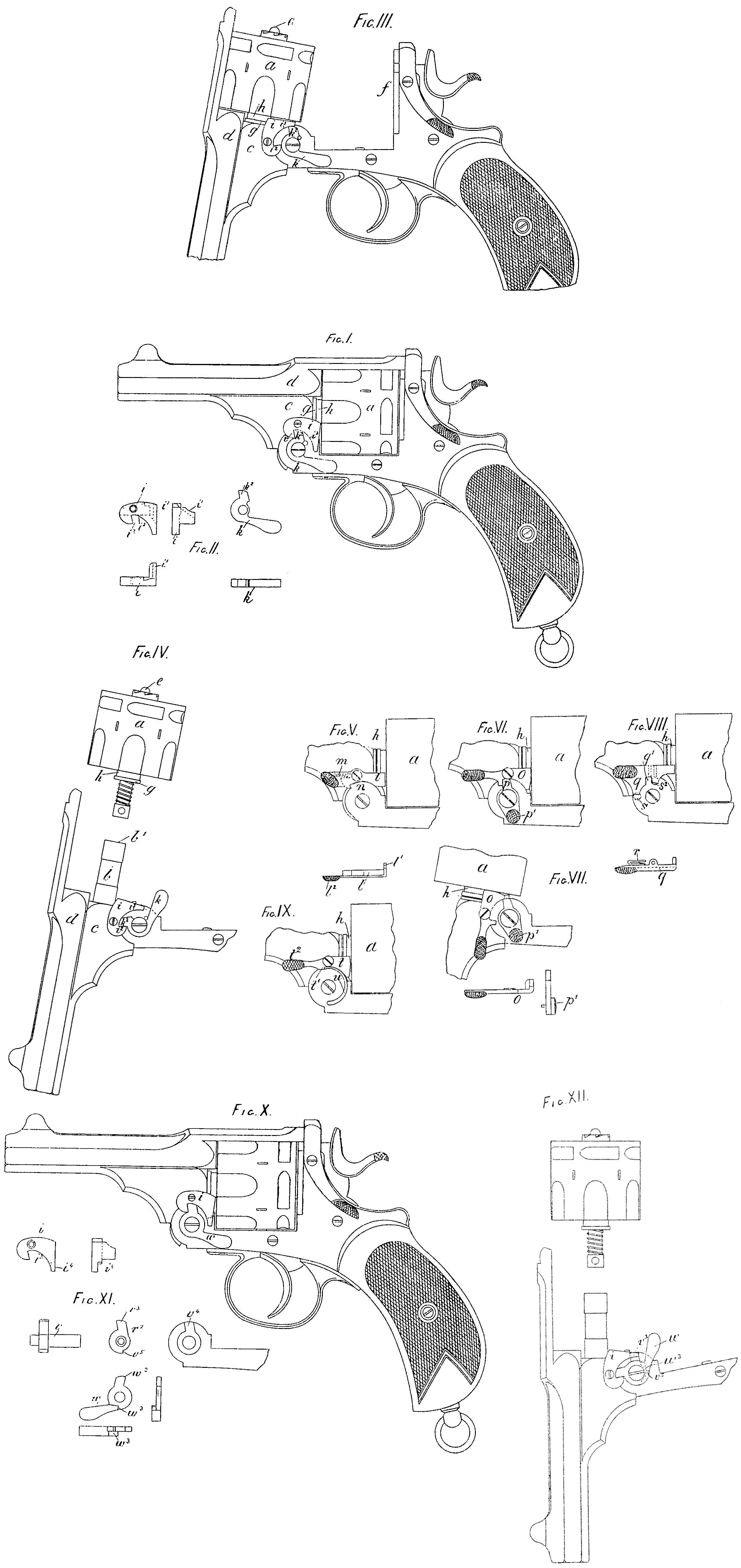
Figure I shews a side elevation of a Webley revolver closed ready for firing, and having my invention applied thereto.
Figure II shews details, and
Figure III shews the revolver opened ready for loading, the extractor having made its outward traverse and returned home.
Figure IV shews the dismounting of the cylinder from its axis.
Figures V, VI, VII, VIII, IX, X, XI and XII shew various modifications of my improvements.
The cylinder a is mounted on a plain axis b, which is firmly fixed into the lump c of the barrel d. A shoulder formed in the axis hole of the cylinder abuts against the rear end b¹ of the axis b to prevent,undue.forward movement of the cylinder a; and its backward movement is prevented by a teat w, which comes nearly in contact with the standing breech f When the revolver is closed. The cylinder is not otherwise fastened to the axis.
On the front end of the cylinder is a short tubular projection or sleeve g, surrounding the axis b; and around this sleeve a groove h is cut for the purposes hereinafter described, namely the holding and releasing of the cylinder as required.
On the lump c of the barrel a lever i is pivoted, and this lever has a claw, i¹ Figure 11, to gear into the groove h in the sleeve piece g on the front end of the cylinder a.
This claw i¹, when in gear with the groove, holds the cylinder on its axis against any longitudinal movement; and when withdrawn from the groove allows such movement.
As shewn in Figures I to IV the engagement and disengagement of the claw in and from the groove h are effected in the following ways.
A lever k is pivoted on the axis of the joint of the body of the revolver, and acts upon the lever. When the revolver is closed, as in Figure I, the lever k presses against the arm i² of the lever i, and so withdraws the claw i¹ from the groove h. The cylinder is thus left free to revolve for shooting without any friction of the claw and groove.
The cylinder is efficiently held between the end b¹ of the axis and the teat e abutting on the standing breech f as before mentioned.
As the revolver is being opened the arm k² of the lever k acts upon the cam i³, formed on the under side of the lever i, and holds the claw firmly in gear with the groove h.
It is thus impossible for the cylinder to slide off the axis while the extractor is making its traverse, nor can it slide off even when the revolver is fully open as is shewn in Figure III.
If, the revolver be now closed all the parts will assume the positions shewn in Figure I.
But, if it be desired to dismount the cylinder from its axis, the lever k is pushed round to-the position shewn in Figure IV, and the claw i¹ is thus with drawn from the groove h, and the cylinder is drawn off the axis. When the cylinder is remounted on the axis the revolver may be closed without touching the lever k, as the mere act of closing the revolver will carry k to its normal position as in Figure I.
It will thus be seen that this method of holding and releasing the cylinder fulfils the conditions required, namely:— (1) A. free cylinder when the revolver is closed. (2) The cylinder securely held during the act of opening and extraction, and when fully open. (3) An easy means of dismounting the cylinder from its axis, and remounting it on the same.
And it is to be noted that all the motions are positive and automatic, except releasing the cylinder for dismounting.
Figure V shews another form, where a lever (is pressed by a spring m so as to, cause a claw l¹ to gear in the groove h. A cam n on the joint of the body acts on the under side of the lever f to engage the same with the groove h when required, and also-to cause its disengagement as required.
When the revolver is fully open the pressure of the spring only holds the claw l¹ in the groove h, and hand pressure on the lump l² enables the cylinder to be dismounted or remounted.
Figure VI shews another form. Here the lever o is acted upon by a limb p which causes its engagement and disengagement according as the revolver is open or closed.
When fully open, as shewn in Figure VII, the cylinder may be dismounted by pushing the lump p¹ so as to free p and o from each other, thus allowing o to be disengaged from the cylinder.
Figure VIII shews a form where the lever q is pivoted so as to act at a right angle to those levers previously described.
The spring r holds the lever q in gear, with the cylinder, and the two studs s¹ and s², carried on the body joint effect the necessary automatic engagement and disengagement of the lever according as the revolver is closed, opening or opened. To dismount or remount the cylinder the stud s¹ is brought to the gate q¹ in the lever q, and the lever is then pressed by hand.
Those parts of the lever g on which the two studs s¹ and s² act are formed on inclines.
Figure IX shews a form of my invention having a lever t and a curved spring u, the latter being fixed on the joint of the body. When the revolver, is closed the parts are in the position shewn in the drawing, The end of the spring u therefore presses the lever t— by means of the shoulder t¹ — out of gear and leaves the cylinder free.
But as the revolver is opened the spring u holds the lever t in gear. The cylinder can be dismounted and remounted by pressing on the lump t².
Figures X, XI and XII shew a further modification of my improvements.
In this case the joint pin v is provided with a head c² having on the same a stud or lump v³ to act on the cam of the lever i.
The stud or lump v³ fits into a groove v⁴ in the joint of the body and hence the said stud or lump v³ becomes a fixture so far as the joint of the body is concerned, but as the revolver is opened or closed the stud or lump c³ has a traversing motion along the curve of the cam i² of the lever i and so fulfils the greater part of the functions of the arm k² Figures I, II and III.
The difference is that when. the revolver is fully opened the stud or lump v³ is cleared from the cam i² and the cylinder might be drawn off the axis. To prevent this the lever w closely resembling the lever k is placed over v² and this lever performs exactly similar functions to the lever k in Figures I, II and III.
The action of a revolver constructed as in Fig, X so far as concerns my present invention is as follows; when closed the parts occupy the positions shewn by Fig. X, that is to say the lump w² of the lever w lies directly over the lump v⁵ and both lumps unite in holding the lever i clear of the groove h. If now the revolver be opened the lever w will be in the position occupied by k in Figure III, and the lump v³ will be under w² and the cylinder will be securely held in position because the lump w² keeps the lever i in gear with the groove A. If it be desired to dismount the cylinder the lever w is pushed into the position shewn in Figure XII, so as to free the lever i from the groove h. The lump v² of course remains in the position shewn in Figure XII, but as before explained in this position it is free from contact with the cam i³ which is partly cut away for this purpose as shewn at i⁴ Figure XI. The shoulder v⁵ on the limb v² and the shoulder w³ on the lever w are to insure that when the revolver is being closed the lever w shall be brought into the position shewn in Figure X no matter what position it may occupy when the revolver is open.
Having now particularly described and ascertained the nature of my said invention, and in what manner the same is to be performed, I declare that what I claim is:—
1. The holding and releasing of the cylinders of revolving firearms by means of the mechanism set forth described and illustrated.
2. The mechanism described and illustrated by Figures I, II, III and IV for holding and releasing revolver cylinders.
3. The mechanism described and illustrated by Figure V, for the like purposes.
4. The mechanism described and illustrated by Figures VI and VII, for the like purposes.
5. The mechanism described and illustrated by Figure VIII, for the like purposes.
6. The mechanism described and illustrated by Figure IX, for the like purposes.
7. The mechanism described and illustrated by Figures X, XI and XII, for the like purposes.
Dated this 4th day of November 1891.
W. J. WHITING.