
Britain 13994
A.D. 1852 № 13,994
Needle Guns.
KUFAHLS SPECIFICATION.
TO ALL TO WHOM THESE PRESENTS SHALL COME, I, George Leopold Ludwig Kufahl, of Christopher Street, Finsbury, London, Engineer, send greeting.
WHEREAS Her present most Excellent Majesty Queen Victoria hy Her Royal Letters Patent, under the Great Seal of the United Kingdom of Great Britain and Ireland, bearing date at Westminster the Third day of March, in the Fifteenth year of Her reign, did, for Herself, Her heirs and successors, give and grant unto me, the said George Leopold Ludwig Kufahl, Her especial licence, full power, sole privilege, and authority, that I, the said George Leopold Ludwig Kufahl, my exors, admors, and assigns, and such others as I, the said George Leopold Ludwig Kufahl, my exors, admors, or assigns, should at any time agree with, and no others, from time to time, and at all times during the term of years therein expressed, should and lawfully might make, use, exercise, and vend within England, Wales, and the Town of Berwick upon Tweed, within the Islands of Jersey, Guernsey, Alderney, Sark, and Man, and in all Her Majesty’s Colonies and Plantations abroad, my Invention of “Improvements in Fire-arms,” in which said Letters Patent is contained a proviso, requiring that I, the said George Leopold Ludwig Kufahl, by an instrument in writing, under my hand and seal, shall particularly describe and ascertain the nature of my said Invention, and in what manner the same is to be performed, and shall cause the same to be enrolled in Her said Majesty’s High Court of Chancery, within six calendar months next and immediately after the date of the said in part recited Letters Patent.
NOW KNOW YE, that in compliance with the said proviso, I, the sad George Leopold Ludwig Kufahl, do hereby declare the nature of my Invention, and in what manner the same is to he performed, to be particularly described and ascertained in and by this present instrument in writing, as follows, reference being had to the Drawings hereunto attached, and to the letters and figures marked thereon, that is to say:—
My said Invention relates to various novel and useful improvements in that class of fire-arms ordinarily known as needle guns. My previous improvements in the same class of fire-arms, under the title of “Improved Construction of Guns and Cannons, and Manufacture of Cartridges for the Loading or Charging thereof,” have been protected by Letters Patent, bearing date the Eleventh day of January, One thousand eight hundred and fifty, and granted to Matthew Urlwin Sears, of Burton Crescent, London, as a communication from me. The objects of the present Letters Patent consist of various mechanical arrangements, apparatus, or means whereby the lock mechanism of fire-arms on the needle principle, whether shot guns, rifles, pistols, or repeaters, is made more durable, safe, and efficient than heretofore, and these improvements are entirely distinct from and unconnected with the subject of the said Letters Patent granted to the said Matthew Urlwin Sears. And in order that my said Invention may be readily understood, I shall now proceed to describe the various Figures on the Sheet of Drawings here-unto attached.
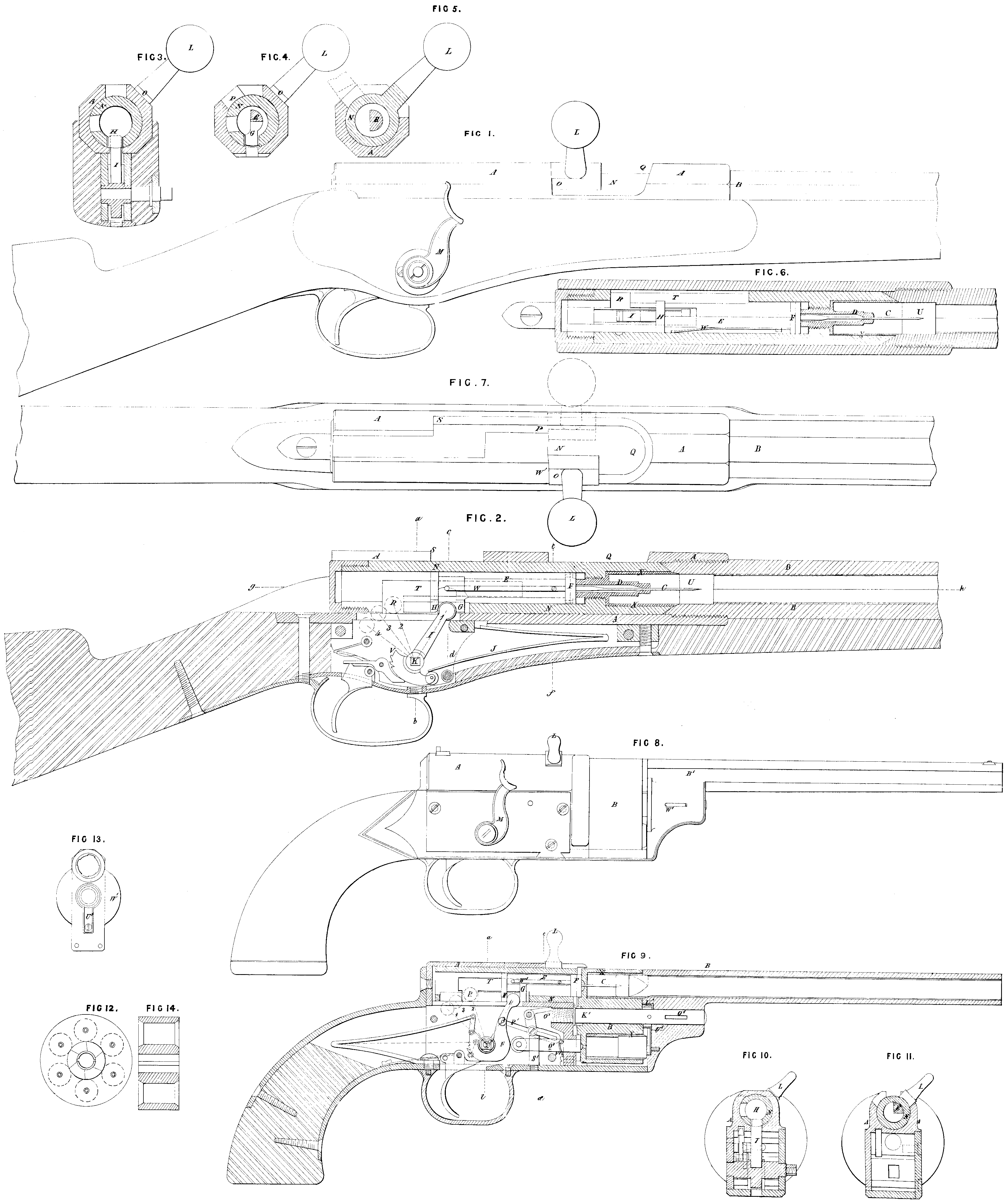
Figures 1, 2, 3, 4, 5, 6, and 7, on my Sheet of Drawings, illustrate the application of my improvements to an ordinary rifled needle gun. Figure 1, is an external side elevation of the lock portion of a needle rifle; and Figure 2, is a vertical longitudinal section of the same parts corresponding. Figure 3, is a transverse vertical section through the lock, at the line a, 8, in Figures 1 and 2. Figure 4, is a similar transverse section, a little further forward ate, @ in Figure 2; and Figure 5, is a third section still further forward, at the line e, f in Figure 2. Figure 6, is a horizontal longitudinal section, along the line of the bore of the barrel and the lock cylinder, as at g, h, in Figure 2; and Figure 7, is an external plan of the Jock and its details.
In carrying out my several improvements have merely retained the outside tube or socket A, screwed into or made in one piece with the barrel B, the needle C, with its guide D, and the lever handle J, as used in the common Prussian needle gun, such portions being common to all needle guns. The other details of the ordinary gun I have cither laid wholly aside, or have so modified them as to suit the particular intention of my improvements. The igniting needle C, is screwed into a conductor E, carrying at its fore end a piston F, well packed with some elastic material, say stout leather, and the other or hind end is formed with a stud G, and disc H. The needle conductor E, is capable of actuation by the tumbler J, which has a rounded head for that purpose, This tumbler is set on a fixed stud centre K, near which it is actuated by the flat main spring J, and a sear, scar spring and trigger, and its axis projecting through the gun stock carries a cocking lever M. As the parts are delineated in the Drawings, they are in the position arising from the lock being at rest, or just discharged by the needle in passing into the priming. The head of the tumbler rests on the stud G, forcing the needle conductor and its piston up to the projecting hind end of the needle guide, so as to prevent the escape of the gaseous products of the explosion at this point, which escape is a very serious objection to the ordinary needle arms, especially with powerful charges. The head of the tumbler in this position, as marked 1, stands up through two corresponding slots, one in the external fixed tube or socket A, and. he other in the inner moveable tube N; and hence the latter cannot now be moved round until the withdrawal of the tumbler head, At the same time the abutment O, of the inner tube is firmly interlocked with a shoulder of the external tube A, as represented in Figure 1.
Now in order to withdraw partially the tube N, from the outside one for loading or cleaning, the abutment O, is first to be brought opposite to a longitudinal slot P, on the left side of the external tube A, so that the breech of the gun can never be opened either wilfully or accidentally, either in the act of firing or for the purpose of introducing a charge, whilst the tumbler is in this position, and whilst the needle protrudes at all from its guide. This arrangement constitutes one of the means provided for insuring perfect safety in handling the gun, such safe-guard being entirely wanting in all other needle guns which may be opened at the breach and charged whilst the needle stands out more or less from its guide, so that the charge is thus liable to accidental explosion. When the breech is to be opened for the introduction of a charge through the loading hole Q, the lock is, in.the first instance, to be brought to half cock. This movement will carry the tumbler to the position indicated by the dotted line 2, in Figure 2, and the action causes the head of the tumbler to act on the face of the lower projecting portion of the disc H, of the needle conductor, and thus to draw back the needle to screen it inside the needle guide. At this position of half cock, but at no other throughout the entire range of action, the tumbler head is directly opposite a transverse slot R, formed in the left side of the inner moveable tube or chamber N, and arranged to receive the tumbler easily, so that the inner tube may then be turned partially round to the left by means of its lever handle L. When this movement has been accomplished the abutment of the lever stands opposite the longitudinal slot P, of the outside tube or socket A, as represented by the dotted lines in the plan Figure 7, the amount of turn being accurately determined by the bringing up or the bearing of the abutment O, against the left side of the longitudinal slot P. In this-condition the slot P, allows of the inner tube N, being slided backwards until the abutment O, reaches the point S, so as to uncover the loading hole, the head of the tumbler meanwhile entering a second longitudinal slot T, of the inner tube, which latter slot communicates with or opens into the transverse slot R. The piece is now ready for loading, and while open at the breech for that purpose the tumbler. and consequently the main actuating spring J, are entirely disconnected from the needle conductor and needle, the stud G, being passed to the right side of the tumbler head. This contrivance is the second means of safety not to be found in any other class of needle gun. The cartridge having been introduced through the loading hole Q, into the space U, the inner moveable tube N, must again be pushed forward by means of its handle. This action covers up the charging hole, and the
movement is rendered complete by turning the lever handle L, back again to the right, so as to interlock the abutment O, with the shoulder. W¹, of the socket A, and all this must be done. before the tumbler can act on the needle conductor. As the gun is now in a condition to be fired the lock may be brought to fill cock, as indicated by the third radial dotted line 3, of the tumbler’s position in Figure 2. In this position of the details, the head of the tumbler standing up at once in the lower longitudinal slots of both the outer and inner tubes, prevents the inner one from being turned, so that there is no possibility of the loading hole being opened. By this means it is, that the arm is rendered perfectly safe in handling, for the breech cannot be opened for loading or any other purpose, nor can it fly open accidentally so long as the tumbler, main spring, and trigger have any communication with or power of action on the needle, which is the only means of firing the charge. To facilitate the periodical cleansing of the gun, a simple means is provided for the entire withdrawal of the inner tube N, from its socket, and its replacement without trouble or annoyance. This is done. by first bringing the inner tube to its second position, or that which it occupies during loading, when the abutment of the lever handle L, is drawn back into the longitudinal slot P, until it reaches the point 5, the lock being first brought to half cock to allow of this movement, as already described. The tumbler must now be drawn back to the extent of two notches, that is until the notch V, which is one notch beyond full cock, shall catch upon the detent, and this brings the tumbler to the position of the furthest dotted line marked 4. With the tumbler in this position its head is brought entirely beneath and clear of any part of the inner tube N, so that the latter may be at once drawn out of its socket by means of its handle L. When cleaned, the tumbler being in the position 4, the needle conductor is brought to the position in tube N, which it occupied when that tube was withdrawn. The tube is then reinserted at the open end of the socket, and is then pushed forward at once to the position for loading. The lock is then lowered to half cock and the loading hole is closed, as already described. By the contrivance of the position 4, of the lock an important advantage Is gained, for without it the inner tube could never be wholly with-drawn from its socket, nor could the gun be effectually cleansed without removing it from the stock, and unscrewing the lock. After loading, it the piece is not to be fired at once, the lock is kept at half cock, or it may be let down to the position of rest. This latter position, however, is only to be arrived at when the charge is in by bringing the abutment O, of the lever handle opposite the longitudinal slot P, in the external tube. Tt is this feature of the engagement and disengagement of the needle with the tumbler and main spring which constitutes an essentially distinct feature of safety of action in my improved gun, for the ordinary needle guns must be kept either at half or full cock when loaded, otherwise the needle would enter and explode the charge. Of the minor details, with the assistance of which the accuracy of the various movements of the lock is insured, the mode in which the piston is caused to retain the position assigned to it while the lock is at half cock, and the loading hole opened for receiving a charge, or other purposes, is very important. To give this holding power a small flat spring W, is adjusted on the right side of the needle conductor, and a small projection on this spring, as represented in Figure 6, falls to a recess in the interior of the inner tube whenever the lock is brought to half cock. This gives the spring a slight hold upon the piston, sufficient to stay it until the latter is forcibly drawn along by the lock action. To prevent the escape of powder gas, or the gases resulting from the explosion of charge, at the joint between the termination of the barrel and the end of the inner tube N, the projecting open end of the latter may be turned down to a knife edge, so as to furnish a thin closely fitting and slightly elastic exterior bearing surface in contact with the interior of the barrel end, to form a tight joint when the loading hole is closed. But instead of this contrivance I prefer to insert into the front open end of the tube N, a short thin clastic tube X, of copper, or other suitable metal, which being fast in the tube N, moves with it, and it is left projecting a slight distance beyond the end of the tube, so as to enter a short distance into the end of the barrel, when the breech is closed for firing. This tube being very thin at the edge becomes expanded and pressed from within outwards, against the interior of the barrel by the effect of the explosion when the piece is fired, hence the joint is effectually closed and the gases are prevented from escaping, just as the cup leather of a hydrotatic press prevents the escape of water. For the best guns this thin joint tube is of platinum, so as to last for a very long period. Both these kinds of joints are further assisted in their accuracy of fitting by turning an external cone on the end of the inner tube N, to fit to a similar internal cone in the barrel end. The flat main spring J, is substituted for the helix ordinarily employed for actuating the lock mechanism of needle guns, as being much more durable and satisfactory in its action, and an important feature exists in the external cocking lever M, the position of which at any angle at once points out whether the lock is shut down at rest, or at full or half cock, or on the last notch. Although I have herein-before referred to the use of cartridges in my improved fire-arms, as affording the greatest facilities for speedy loading, J may remark that they are not by any means absolutely required for the effective service of the gun, for instead of cartridges, the powder may be easily measured into the breech, to lay round the needle guide, and the bullet, with the priming, may be thereafter inserted. And, although I have herein-before referred especially to the construction of needle rifles on my improved principle, it will be obvious to the practical gun smith that muskets, carabines, shot guns, pistols, and other arms may be so fitted and managed, as I have described. But the construction of needle revolvers, or repeating pistols, which has never hitherto been attempted, necessitates the introduction of certain modifications of the details, which I shall now proceed to describe. Figure 8, on my sheet of Drawings is a longitudinal side elevation of a repeating needle pistol, as fitted with my improvements. Figure 9, is a vertical longitudinal section of the same corresponding. Figure 10, is a trans-. verse section at the line ¢, 6, through the centre of the tumbler spindle in Figure 9, and Figure 11, is a second traverse section through the line ¢, d, in Figure 9. Figure 12, is a front end elevation of the revolving or repeating chamber, forming the magazine of charges, and; Figure 13, is an end elevation of the hindmost open end of the barrel. The pistol is delineated in the Figures as unloaded, and having its lock put down or at rest. The fixed external tube or socket A, is formed at the upper side of its front end, next the barrel, with a longitudinal and a transverse slot meeting in cruciform fashion, for receiving and allowing of the requisite movements of the lever handle L, of the inner or move-able.tube, containing the needle conductor E, with its packed piston F, the stud G, and disc H, as in the same details of the needle rifle. The lower part of the socket A, is extended downwards at its front end and on the left side, forming in combination with an adjustable plate on the right side and the trigger plate, a rectangular box for the reception of the tumbler I, the main spring J, the sear spring upper part of trigger; as well as those parts by-which-the revolving magazine B, containing the charges is made to revolve. When unloaded and at rest, with the tumbler in the position 1, as delineated in Figure 9, the tumbler head projects upwards through the corresponding lowest longitudinal slots in both tubes, so as to prevent the rotatory movement of the inner tube. At the same time the needle C, projects into the highest chamber (for the time being) of the magazine, thus also preventing the latter from revolving. A needle guide is in this arrangement quite unnecessary as the needle is so short that it may be used in the interior of the chambers. In commencing to load from the position delineated in my Drawings, Figure 9, the needle is first of all withdrawn from the most elevated chamber; this movement being accomplished as in my needle rifle, by carrying back the tumbler I, to half cock, that is to the position of the dotted line 2, by means of the external cocking lever M. The loading lever handle LL, is then turned over to the left side as indicated by the dotted lines in Figure 10, whereby the head of the tumbler entering the transverse slot R. in the inner tube is disconnected from the needle conductor. The charges may then be most expeditiously entered into the ring of chambers by removing the barrel B¹, of the piece from the centre pin or arbor K¹, on which the magazine revolves. This gives tree admission to the whole series of chambers and the charges consisting of powder and a bullet with suitable priming may be at once entered into the chambers successively, a washer of paper, thin felt, or other suitable material being first laid in the bottom or closed end of each chamber to cover up the small hole by which the igniting needle C, is to enter. When the chambers are all duly charged the barrel is replaced and held in position by a transverse pin O, and the lever L, being still on the left side, the tumbler may be let down to set the lock at rest. In this movement the head of the tumbler moves forward in the left hand longitudinal slot T, of the inner tube, which slot is now on the bottom: side and is in accurate correspondence with the bottom slot of the external socket, and being disconnected from the needle conductor E, the tumbler leaves the latter behind to remain in the same position-which it occupied on the occurrence of the half-cock movement. Here it is kept by a flat side spring W, precisely as in the rifle. In this state, as the needle cannot by any means reach the priming or detonating compound in the interior of the chambers of the magazine, the pistol cannot be discharged, and it may be carried about and. subjected to the roughest usage without the slightest danger. When the arm is to be fired the tumbler is again moved to half-cock by the lever M, the lever handle L, being returned to the right hand position as in Figure 8, so that the tumbler head regains its position between the stud G, and disc H, of the needle conductor. On going on to full-cock or to the position of the dotted line of tumbler 3, the magazine B, will revolve one-sixth round, six chains being here used. This action arises from the effect of a small bell crank lever O¹, the short lower arm of which carries a pin fitting into a long slot in the link piece P¹, attached to the tumbler. The charge in the highest chamber may now be fired, and afterwards the remaining five in succession, by going at once to full-cock and drawing the trigger. When the lock is to be cleaned the inner tube N, is to be removed altogether from its outer socket, carrying with it the needle conductor, the barrel and magazine being first slipped off their arbor K¹. But to permit of the removal of the inner tube with its internal mechanism, the tumbler must be brought to the position of the dotted line 4, when its head will be disengaged just as in the rifle. The means of preventing the escape of the gases of explosion, namely, the piston F, of the needle conductor shutting the needle hole in conjunction with the thin metal tubes X, are the same as in the rifle, only that the elastic tubes X, are inserted into the chambers of the revolving magazine B, where the discharges take place. To bring the front part of the highest chamber tube into the open end of the barrel, and to hold it there during the discharge, a strong horizontal bolt or locking piece Q¹ is fitted into the lower part of the lock apparatus. This bolt works through a vertical guide S¹, screwed into the trigger plate, and its front end is kept constantly in contact with the inner or back face of the magazine, whilst its opposite end similarly bears by means of a small pulley upon a rounded prominence on the tumbler. Whilst the arm is at half or full cock, the magazine and the bolt Q¹, are retained in a back position and free from contact with the barrel end by a small blade spring U¹, situated between the front of the magazine and the barrel end, so that the thin tubes X, are all clear of the latter. But so soon as the trigger is drawn, the rounded prominence of the tumbler presses forward the bolt Q¹, and thus forces the magazine up against the barrel end, pushing the prominent end of the thin tube into the open end of the barrel, so as to close up the joint in a most efficient manner before the needle can reach the priming or detonator and explode the charge. The recoil of the magazine due to the explosion is not taken off by the main spring but by the strong axis K, of the tumbler, the bolt Q¹, being in a horizontal line with that centre. Besides these services the bolt Q¹, steadies the magazine as the latter revolves, and provides that a needle hole shall always be in its proper place for the entrance of the needle. It affects this with the assistance of the slight spring V¹, which acting on a pin in the bolt Q’, constantly tends to force a small projection at the front end of the latter into the lowest needle hole after each revolution of one-sixth. Io prevent any dislodgement of the charges in the chambers by the recoil, the end of the barrel is provided with an enlargement W¹, which all but touches the points of the bullets in the five chambers not being fired, and thus the charges are entirely prevented from moving forward by the concussion. Figure 14, on my Sheet of Drawings represents a vertical section of a metal disc pierced with six holes to correspond with the magazine chambers, and having a central hole to fit the arbor K¹. This disc is intended for screening the thin projecting edges of the clastic tubes X, from injury during loading by being placed over the face of the magazine. It will be obvious that the same general arrangements are applicable more or less in the construction of repeating needle rifles, carabines, and shot guns.
Having now described and particularly ascertained the nature of my Invention, and the manner in which the same is or may be used or carried into effect, I may observe in conclusion that I do not confine or restrict myself to the precise details or arrangements which I have had” occasion to describe or refer to, as many variations may be made therefrom without deviating from the principles or main features of my Invention, but what I consider to be novel and original, and therefore claim as the Invention secured to me by the herein-before in part re-cited Letters Patent, is,
First, the application and use of the stud and disc, or details substantially of a similar nature, to the needle conductor for the purposes herein-before described.
Second, the system or mode of engaging and disengaging the needle with the tumbler or lock apparatus, as herein-before described.
Third, the application and use of a piston or traversing filling up piece, for the prevention of gaseous escape into the lock.
Fourth, the adaptation of the lock tumbler, for the prevention of the withdrawal of the inner tube or chamber from its socket, except at a certain position of the tumbler.
In witness whereof, I have hereunto set my hand and seal the third day of September, in the year of our Lord One thousand eight hundred and fifty two.
GEORGE LEOPOLD (L.S.) LUDWIG KUFAHI.
Signed, sealed, and delivered in the presence of
Edwin P. Alexander,
Bris. Hunt,
Clerks to Messᶠˢ W, & J. H. Johnson,
47, Lincoln’s Inn Fields.
AND BE IT REMEMBERED that on the Third day of September, in the year of our Lord 1852, the aforesaid George Leopold Ludwig Kufahl came before our said Lady the Queen, in Her Chancery, and acknowledged the Specification aforesaid, and all and every thing therein contained and specified, in form above written; and also, the Specification aforesaid was stamped according to the tenor of the Statute made: for that purpose.
Enrolled the third day of September, in the year of our Lord, one thousand eight hundred and fifty-two.