
US 27526
UNITED STATES PATENT OFFICE.
J. MASLIN COOPER, OF PITTSBURG, PENNSYLVANIA.
IMPROVEMENT IN REVOLVING FIRE-ARMS.
Specification forming part of Letters Patent No. 27,526, dated March 20, 1860.
To all whom it may concern:
Be it known that I, J. Maslin Cooper, of Pittsburg, in the county of Allegheny and State of Pennsylvania, have invented a new and useful Improvement in Revolving-Breech Fire-Arms; and I do hereby declare the following to be a full, clear, and exact description thereof, reference being had to the annexed drawings, forming part of this specification.
My improvement consists in constructing revolving-breech fire-arms operating, either by hammer or trigger, in such a manner that the same fire-arm may be used either with cylinders closed at the rear end and furnished with cones for percussion-caps adapted to firing loose ammunition or with cylinders bored through from end to end and adapted to firing fixed ammunition charged at the rear end.
I am aware that fire arms have been constructed with revolving cylinders open at both ends to fire fixed ammunition, and also that fire-arms with revolving cylinders closed at the rear end and furnished with nipples for percussion-caps adapted to loading with powder and ball in the usual way are well known; but my improvement lies in the constructing and arranging of the parts of revolving fire-arms so as to be adaptable to firing either kind of ammunition by simply changing the revolving breech.
This improvement has not been heretofore successfully attempted, probably owing to the fact that revolving fire-arms designed to use cylinders bored through from end to end for firing the fixed ammunition require that the rear end of the bore should be covered by the recoil-shield of the lock or some equivalent device; otherwise they would be very unsafe, owing to the liability of the charge blowing out behind and of communicating fire to other chambers than the one which is designed to be discharged, which prevents the hammer being so arranged as to strike the cartridge or cap in a line with the bore of the chamber and barrel.
To enable others skilled in the art to construct and use my improved fire-arm, I will proceed to describe its construction and operation, referring to the accompanying drawings, in which—
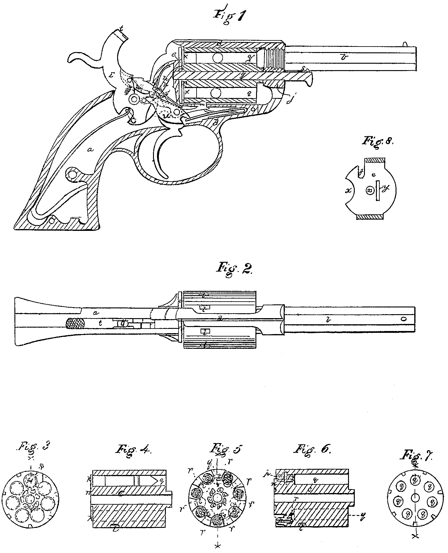
Figure 1 is a sectional side view of a revolving breech pistol constructed with my improvement. Fig. 2 is a top view of the same. Fig. 3 is a rear end view of a cylinder or revolving-breech loaded with cartridges for fixed ammunition, showing the position of the end of the hammer when it strikes the cartridge in firing the pistol. Fig. 4 is a longitudinal section through the axis of the cylinder seen in Fig. 3. Fig. 5 is a rear end view of a revolving breech or cylinder closed at the rear end, excepting the aperture in the cones. Fig. 6 is a longitudinal section through the axis of cylinder Fig. 5. Fig. 7 is a front end view of both kinds of cylinder as represented in Figs. 4 and 6. Fig. 8 is the recoil-shield.
In the several figures like letters of reference denote similar parts of the pistol.
In the drawings, Figs. 1 and 2, a is the stock of the pistol, b the barrel, c a revolving cylinder or chambered breech, the construction of which will be more particularly described hereinafter. The cylinder c may be attached to the lock-frame in any convenient manner, but so as to be readily removable for the purpose of changing the cylinder, and yet strong and secure, and allowing the breech to revolve freely on its axis. This I accomplish as follows:
d is the frame of the pistol, in an opening in which is placed the cylinder between the recoil shield e and the front end or bracket f of the frame. The barrel is screwed into or other wise attached to the bracket fat the proper height to range with the chambers in the breech. The breech or cylinder c is secured in its place in the lock-frame by a movable pin or spindle, g, which is inserted through a hole in the bracket f, just under the barrel, and extends through the central bore of the cylinder c, entering the recoil-shield e. This pin is kept in place by a spring, s, in its head, which catches in a notch in the under side of the barrel b. (See Fig. 1.)
To remove the cylinder c from the frame of the pistol it is only necessary to withdraw the ping and the cylinder will drop out, and the same or another cylinder may be as speedily substituted. The recoil-shield e (see Fig. 8) is a metallic disk forming part of the lock frame of the pistol and situate concentrically with the cylinder c. It has a hole, x, in the center, into which the spindle g enters, and a groove or slit, y, on one side of the center, through which the point of the finger h, passes to rotate the cylinder c. There is also a semicircular space, 2, at the right side to allow the exploded caps to fall off from the cones of the breech, and an opening, j, on top of the disk a little at one side of the center, through which the end of the hammer passes to strike the cartridges or percussion-caps, as the case may be.
The revolving cylinders used are of two kinds. (Shown in Figs, 3 to 6.) One kind of cylinder, c, (being that shown in the pistol in Fig. 1) is constructed in the ordinary way for firing fixed ammunition or cartridges, the chambers q being bored of uniform diameter throughout, both ends being open, as seen in Figs. 1 to 4. The neck 1 of the cylinder is very short, so that when the cylinder is loaded with the fixed ammunition, as in Fig. 4, the head of the cartridge k will be flush with the end of the neck in of the breech, both touching the face of the disk which forms the recoil-shield e. The ratchet-grooves i i, &c., on the neck of the cylinder are sunk, so as to present no obstacle to the recoil-shield e, lying close up against the end of the cylinder c and the heads of the cartridges k, as before described. On the circumference of the cylinder c are notches l, into which the head of the locking-lever m fits, to secure the cylinder from rotation at the time of the discharge of the pistol. The other cylinder, c’, Figs. 5 and 6, is adapted in its construction to the firing of loose ammunition or powder and ball in the usual way, the cylinder c’, being furnished with cones or nipples p p, to receive the percussion-caps. The length and diameter of the cylinder c and the number of the chambers q it contains correspond exactly with the cylinder c, so that they both fit the same pistol equally well, and the neck n and ratchet-grooves i are similarly constructed and situate, so that the finger h operates on it in the same way to cause the proper rotation of the cylinder previous to each discharge. The relative situation of the cones p and chambers q is different from that of fire-arms of ordinary construction, in that the nipples are not set in the line of the axis of the chambers, but to one side, as seen in Fig. 5, where the dotted circle between the cones indicates the position of the chamber, there being a small cylindrical aperture (shown by dotted lines at r r in Figs. 5 and 6) connecting the bore of each cone with the cylinder at one side of it. The object of this construction is to adapt the cylinders c and c’ to use in the same pistol and the necessity of Some such arrangement will be apparent by examining Figs. 3 and 5, which exhibit the rear ends of the cylinders c and c’, respectively. In both of these figures the perpendicular dotted red line x x passes through the axis of the cylinder and the axis of the bore of the barrel and of the chamber q’ of the cylinder which is to be discharged.
With the use of fixed ammunition and cylinders open at both ends, as in Fig. 4, it is necessary, as before stated, that the recoil-shield e should cover the Whole of the rear end of the chamber q’, which is to be fired, and also more or less cover the heads k of all the cartridges, so as to keep them in place and prevent their interrupting the free rotation of the breech. To accomplish this the hammer t is situate in the pistol-frame to one side of the central line, x x, as seen in Figs. 2 and 3, and its point t’, which strikes the cartridge and caps, is so shaped as to strike the end of the cylinder entirely to one side of the chamber q’, which is to be discharged, as is apparent from Fig. 3, where t’ indicates the shape of the end of the hammer, and shows the point at which it strikes the cylinder, which will be seen to be to one side of the chamber q’, covered by the head of the cartridge k’. The outer circles in Fig. 3 show the circumference of the head of the cartridge, and the dotted inner circles the circumference of the chambers. The head k’ of the cartridge projects beyond the circumference of the chamber, and a hammer strikes a point of this projecting head, which is sufficient to fire the pistol.
Now, if is manifest that if a cylinder of ordinary construction having cones set in a line with the bore of their respective chambers were placed in the pistol thus constructed the hammer would not strike the percussion-cap on the cone, because it would be out of its range and covered by the recoil-shield e. I therefore construct my cylinder c’ for firing loose ammunition or powder and ball, as before described, placing the cone of each cylinder to one side. It will be seen by Fig. 5, which shows the rear end of the cylinder c’, that the end t of the hammer t fairly strikes the end of the cone p, which communicates with the chamber situate in the line x x.
In the lock of the pistol, t is the hammer, u the trigger, v the pawl which holds the hammer t at half or full cock, and w the vibrating tooth on which the trigger operates. The lock is double-action— that is, operates either by hammer or trigger— and rotates and locks the breech preparatory to firing.
The construction of the lock shown in Fig. 1 may be varied— that is, my invention may be applied to revolving fire-arms having various kinds of locks.
Although I have described a specific arrangement of parts for accomplishing my object of constructing revolving fire-arms so that in the same fire-arm may be used either fixed ammunition in cylinders charged in the rear, or loose ammunition in cylinders charged from the front, by the use of two or more cylinders each adapted to its peculiar kind of ammunition, and yet equally adapted to the same fire-arm, yet I do not wish to confine myself to the exact mode hereinbefore described of accomplishing the result, as it is susceptible of modification, as by setting the cones in the cylinder, either perpendicularly or obliquely to its axis, and so constructing the hammer that one part will strike the cones of the one cylinder and another part strike the head of the cartridge in the other cylinder.
The advantages of my arrangement are obvious. As its object is to enable the same fire-arm by mere change of cylinder to be used with either kind of ammunition, a person unable at any time to procure one kind of charge is not thereby deprived of the use of his pistol with the other.
What I claim as my invention, and desire to secure by Letters Patent, is—
1. So constructing and arranging the lock and revolving cylinders of revolving-breech fire-arms, substantially in the manner herein before set forth, as that the same fire-arm may be equally well used either with a cylinder Open at both ends and carrying fixed ammunition charged at the rear or with a cylinder constructed so as to load from the front and carry loose ammunition, or ordinary powder and ball.
2. The mode hereinbefore described of rendering revolving-breech fire-arms susceptible of firing either fixed ammunition loaded from the rear, or powder and ball charged into the front end of the breech, by the use with a single fire-arm of two or more cylinders of different constructions, to suit the different kinds of charge, so arranged, in combination with the lock and barrel 6f the fire-arm, as that either may be used at pleasure.
In testimony whereof.I, the said J. Maslin Cooper, have hereunto set my hand.
J. MASLIN COOPER.
Witnesses:
A. C. Bakewell,
W. Bakewell.