
US 51269
UNITED STATES PATENT OFFICE.
JOSEPH RIDER, OF NEWARK, OHIO, ASSIGNOR TO HIMSELF AND E. REMINGTON & SONS, OF ILION, NEW YORK.
IMPROVEMENT IN REVOLVING FIRE-ARMS.
Specification forming part of Letters Patent No. 51,269, dated November 28, 1865.
To all whom it may concern:
Be it known that I, Joseph Rider, of Newark, in the county: of Licking and State of Ohio, have invented certain new and useful Improvements in Breech-Loading Fire-Arms; and I do hereby declare. the following to be a full, clear, and exact description of the same, reference being had to the accompanying drawings, making a part of this specification, in which—
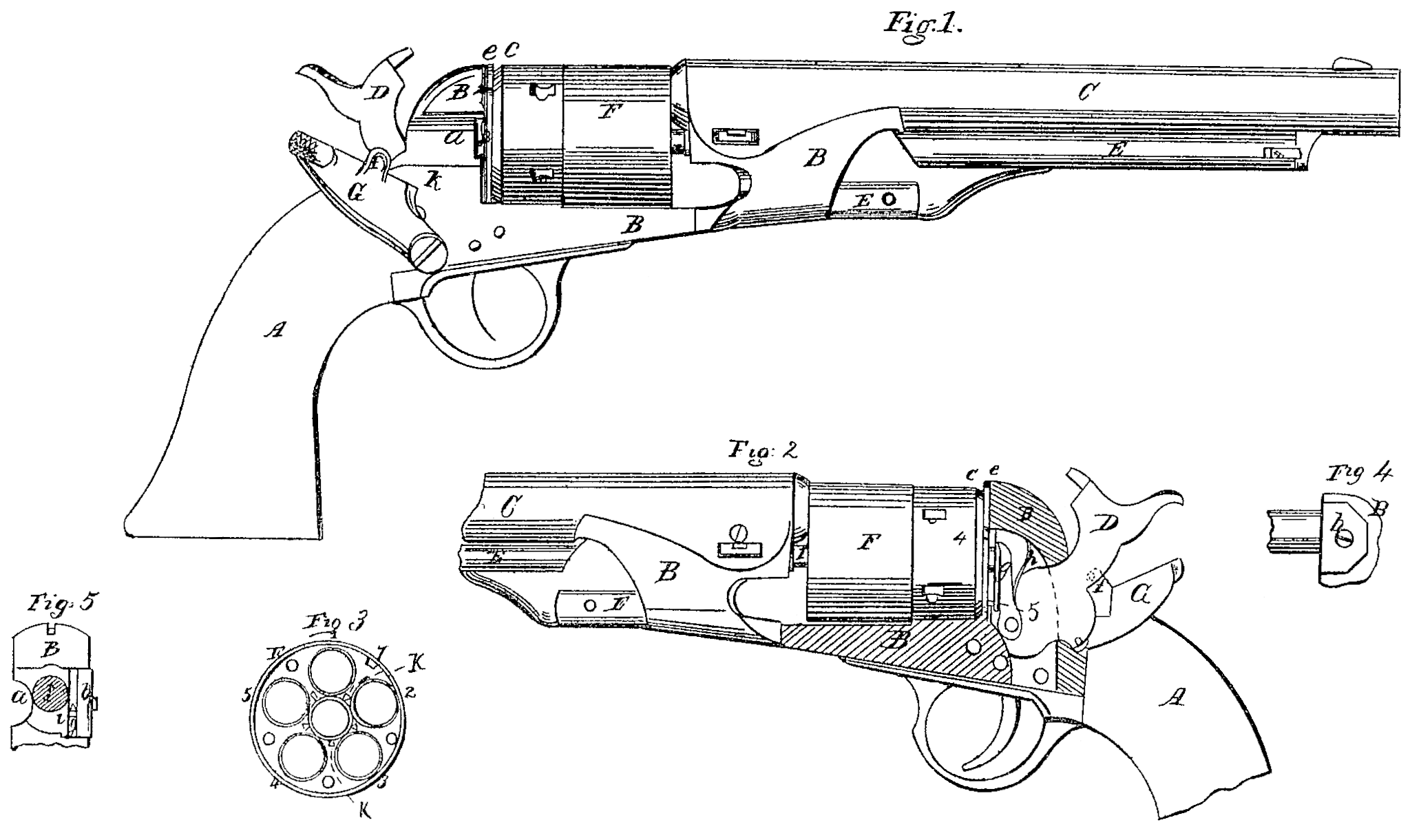
Figure 1 represents a view from one side of the arm. Fig. 2 represents a view from the opposite side thereof, and partially in section, to show the interior arrangement. Fig. 3 represents a rear view of the revolving chambers and cylinder with its appliances. Figs. 14 and 5 represent different views of the pawl-guide, the latter figure showing the pawl in working position.
Similar letters of reference, where they occur in the several separate figures, denote like parts in all the drawings.
One of the objects of my proposed invention is that revolving cylinder fire-arms which are loaded at the front, such as those known as the “Colt” and “Starr” arm, and others of that class of arms, may be converted into breech-loaders, so that metallic cartridges may be used instead of paper ones, or loose powder, and ball or flanged cartridges, instead of cylindrical or conical ones; but the invention is equally applicable to the construction of new arms, designed for metallic cartridges that are to be inserted in the chamber from the rear. And my invention consists, first, in forming a shoulder at the rear of the revolving cylinder, with openings formed in said shoulder opposite each of the chambers, for the jaw of the cartridge-case extractor to pass through, and an extra or additional opening or, openings for said jaw to pass through when the cylinder is charged with cartridges and their flanges close the openings opposite the chambers. And my invention further consists in the use of a pawl-guide that allows the pawl to project just far enough to take hold of the ratchet without dropping into the center bore of the cylinder.
To enable others skilled in the art to make and use my invention, I will proceed to describe the same with reference to the drawings.
Fig.1 represents a Colt’s revolver converted from a loose powder-and-ball loader to a breech-loader, as will be explained. In the first place, to thus alter such an arm, the cylinder must be removed and a new, one made; as the arm, being originally a six-shooter, or having six chambers, can only when changed have five chambers, because the diameter of the cylinder must not be changed, else it would not fit or work in the frame, and more space is required to make the countersink in for the flange of the cartridge-case, and to procure this space in a given-sized cylinder one chain must be left out. Leaving out one chamber, so as to have five, where formerly there were six, involves, of course, a new action of the pawl, for the pawl at each operation of the hammer, which cannot be changed in its motion, must turn the cylinder one-fifth of a revolution, where before the change it turned it one-sixth of a revolution at each cocking of the hammer. And further still, the forming of the countersink around the rear of the chambers for the flange of the cartridge cuts through the ratchet. formed around the center-bore which slips over the center-pin, so that an ordinary pawl would drop into the ratchet too far, or so far as to prevent its action, and hence the pawl must be guarded against this contingency. I have so provided for the working of the arm thus changed from a six to. a five chambered cylinder as that the pawl only, in addition, to the cylinder, need be removed or replaced by others, or rather a lip only, and a guide need be applied to the original pawl. I add a cartridge-case extractor to the arm, but the addition of this piece does. not require anything else to be removed to find a suitable place for it, nor does it interfere with the operation of any other part of the arm.
The stock A, frame B, barrel C, hammer G, and rammer E may remain unchanged, except that the cheeks of the frame in rear of the cylinder may require cutting away, as at a, for the insertion of the cartridges, and on the opposite side for the introduction of the pawl-guide b, and when the pawl-guide is properly placed a piece may be set on over it to fill out the frame so as to cover and protect the chambers.
The new cylinder F is of the same diameter externally as the one removed. It is bored out at its center with the same bore as the one removed, because it is fit over and turns upon the same center-pin, which is unchanged ; but I make upon the rear perimeter of the cylinder a groove, c, and a flange, e, tine side of the groove farthest from the flange being beveled or sloped, as shown in the drawings. On radial lines passing through the centers of the chambers I make openings 1 2 3 4 5, through the flange e, for the jaw f of the cartridge case extractor G to pass through as it draws out the empty case; and intermediate between any two of these radial openings I make an additional opening, 7, for the jaw to pass through when the cylinder is filled with cartridges and they are not to be withdrawn, or when the jaw is entered so as to pass under the flanges of the cartridges and take hold of them. The extractor G has a pressure-spring underneath it to keep it from dropping back and forth loosely.
The pawl g is pivoted to the hammer D, as shown in Fig. 2, and has a spring, h, behind it to throw it out. It, moreover, has upon one side of its point a lip, i, as seen in Fig. 5. The object of this lip upon the pawl is to cause the pawl to turn the cylinder farther by means of the ratchet-teeth k than it would without the lip, for it will be remembered that while the hammer which works the pawl has no change of motion, yet the pawl must turn the cylinder one-fifth, instead of one-sixth of an entire revolution, as it did before. This is accomplished by the lip which keeps the pawl longer on the ratchet, and in its proper position to turn the ratchet, and consequently the cylinder. The lip i must move past the center-pin I, and consequently the center-pin at that point of passing must be slightly cut away to admit of its free motion. The pawl, as shown in Fig. 2, without anything further that there seen to control its motion, would drop into the ratchet and fail to act. It must project just far enough to catch the ratchet, and it must be held back so as not to fall into the ratchet. For this purpose I use the pawl-guide or protector b, which is simply a plate with a lip turned upon it, as shown in Figs. 4 and 5, which allows the pawl to play freely up and down without projecting beyond said plate.
In the pistol or arm herein shown the ratchet is formed around the projection on the end of the cylinder. There are other revolvers where the ratchet is made on the end of the projection instead of its perimeter. In such pistols the pawl may have to be somewhat modified, but in all cases the pawl-guard must be used, or pawl-guide. In what is known as the “Starr” arm the guide may be on the end of the pawl itself, and also on the side, but whether the guide be permanent on the frame, or whether it be combined with and move with the pawl, it is nevertheless a guide, and indispensable in causing the pawl to take the ratchet without projecting too far into it.
Having thus fully described my invention, what I claim therein as new, and desire to secure by Letter’s Patent, is—
1. The groove and flange at the rear of the revolving cylinder, with the openings 1, 2, 3, &c., cut through said flange for the jaw of the extractor to work through, substantially as and for the purpose described.
2. In combination with a pawl for turning a cylinder, a pawl-guide constructed and operating substantially in the manner and for the purpose described.
JOSEPH RIDER.
Witnesses:
W. W. Thomas,
E. Roche.