
US 121199
UNITED STATES PATENT OFFICE.
JACOB RUPERTUS, OF PHILADELPHIA, PENNSYLVANIA.
IMPROVEMENT IN REVOLVING FIRE-ARMS.
Specification forming part of Letters Patent No. 121,199, dated November 21, 1871.
To all whom it may concern:
Be it, known that I, Jacob Rupertus, of the city and county of Philadelphia and State of Pennsylvania, have invented all Improvement in Revolving Fire-Arms, of which the following is a specification:
My invention consists, first, in locking the cylinders of a revolving fire-arm at its front end, instead of beneath or at its rear end; secondly, of a peculiar bolt for thus locking the cylinder; and thirdly, of an economical arrangement of spring retaining-pins for the said bolt and breech-pin or axis of the cylinder.
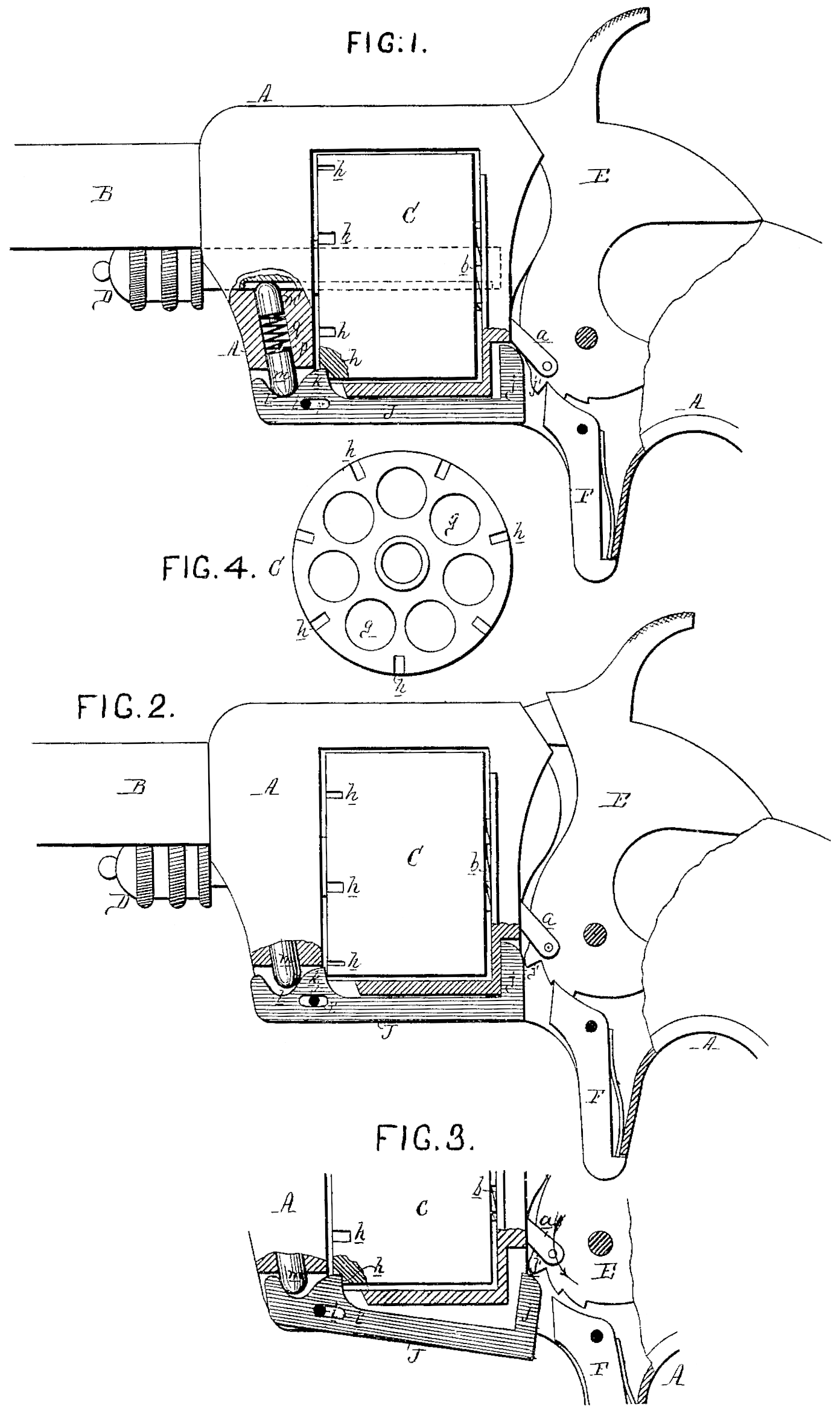
In the accompanying drawing, Figure 1 is a side view, partly in section, of my improved revolver, showing the hammer down and the cylinder locked; Fig. 2, the same, with the hammer drawn back to the position of half-cock and the cylinder unlocked and free to turn; Fig. 3, a detached view, showing the action of the descending hammer upon the cylinder-bolt; and Fig. 4 a front view of the cylinder.
A represents, the frame of the revolver; B, the barrel; C, the cylinder; D, the breech-pin upon which the said cylinder turns; E, the hammer, provided with the usual spring-finger a for revolving the cylinder by means of a notched projection, b, at the rear end of the latter; and F, the trigger.
It has been customary heretofore to lock and prevent the cylinder from turning, excepting when the hammer is at the position of half-cock, by means of a bolt adapted to notches cut in the under side or in the rear edge of the said cylinder. I have found that the cylinder can be more securely locked, especially at the moment of firing, by adapting a bolt to deep notches h cut in the front end of the said cylinder, these notches corresponding in number to and being, in the present instance, formed at points between the chambers g of the cylinder. Bolts of various forms and methods of operation may be used for thus locking the cylinder at its front end, but I prefer to employ a bolt, J, such as illustrated in the drawing. This bolt is fitted to a recess formed for its reception in the frame beneath the cylinder, is held in position by a pin, i, of the frame, which passes through a slot, i, of the bolt, and has a projection, j, at its rear end, arranged to be struck by a lug, j’, on the hammer. A projection, k, near the front end of the bolt is adapted to the notches h in the front of the cylinder, and a curved depression, l, in the upper edge of the bolt receives the rounded end of a spring-pin, m, contained within a recess, p, of the frame.
The operation of the bolt is as follows: When the hammer is drawn back to the position of half cock its lug j’ will strike the projection j of the bolt and cause the latter to slide forward sufficiently to disengage its projection k from and unlock the cylinder. On withdrawing the bolt and continuing to drawback the hammer toward the position of full-cock, the finger a, acting upon the notched projection d of the cylinder, will turn the same to an extent sufficient to bring another of its chambers opposite the barrel; after which, and during the same rearward movement of the hammer, the lug j’ of the latter will be raised to a position above the end of the projection j of the bolt, so that the said bolt may consequently, owing to the action upon the same of the spring-pin m, regain its original position, Fig. 1, and thus again lock the cylinder while the hammer is at the position of full-cock. When the hammer is caused to descend in order to discharge the load its lug j’ will strike the upper end of the projection j of the bolt, and while slipping over the curved surface of the same will turn the said bolt upon its pin i, as shown in Fig. 3. This will cause the projection k of the bolt to enter the notch h of the cylinder to its full extent, and thus hold the said cylinder firmly and prevent any possibility of its turning during the descending movement of the hammer. Just before or as the hammer strikes the cartridge the lug j’ of the said hammer Will pass by and release the bolt, but the latter will still continue to hold the cylinder, owing to the action of the spring-pin m. The spring-pin m and the pin m’, by which the center-pin D is prevented from being entirely withdrawn from the frame, are both contained within the same recess p of the said frame, and are both acted upon by one spring, q, which forces them in opposite directions and into the recessed portions of the bolt J and breech-pin. This, it will be evident, is a more economical plan than that of forming a separate recess and providing a separate spring for each pin.
I claim as my invention—
1. The combination of the-cylinder, notched at its front end, with the locking and releasing devices herein described, or any equivalent to the same.
2. The bolt J, adapted to notches h in the front end of the cylinder, acted on by a spring or spring-pin, m, and having a combined sliding-and-turning movement upon the supporting-pin i, imparted to it by a lug on the hammer, all substantially as specified.
3. The pins m and m’ contained within a recess of the frame and acted on by a single spring, g, by which they are forced in opposite directions into recesses of the bolt J and breech-pin D, all as herein set forth.
In testimony whereof have signed my name to this specification in the presence of two subscribing witnesses.
JACOB RUPERUS.
Witnesses:
Wm. A. Steel
Jno H. Harding.
(123)