
US 165369
UNITED STATES PATENT OFFICE.
JACOB RUPERTUS, OF PHILADELPHIA, PENNSYLVANIA.
IMPROVEMENT IN REVOLVING FIRE-ARMS.
Specification forming part of Letters Patent No. 165,369 dated July 6, 1875; application filed
To all whom it may concern:
Be it known that I, Jacob Rupertus, of Philadelphia, Pennsylvania, have invented certain Improvements in Revolving Fire-Arms, of Which the following is a specification:
My invention relates to certain improvements, fully described hereafter, in the revolving fire-arm, for which Letters Patent No. 121,199 were granted to me on the 21st day of November, 1871.
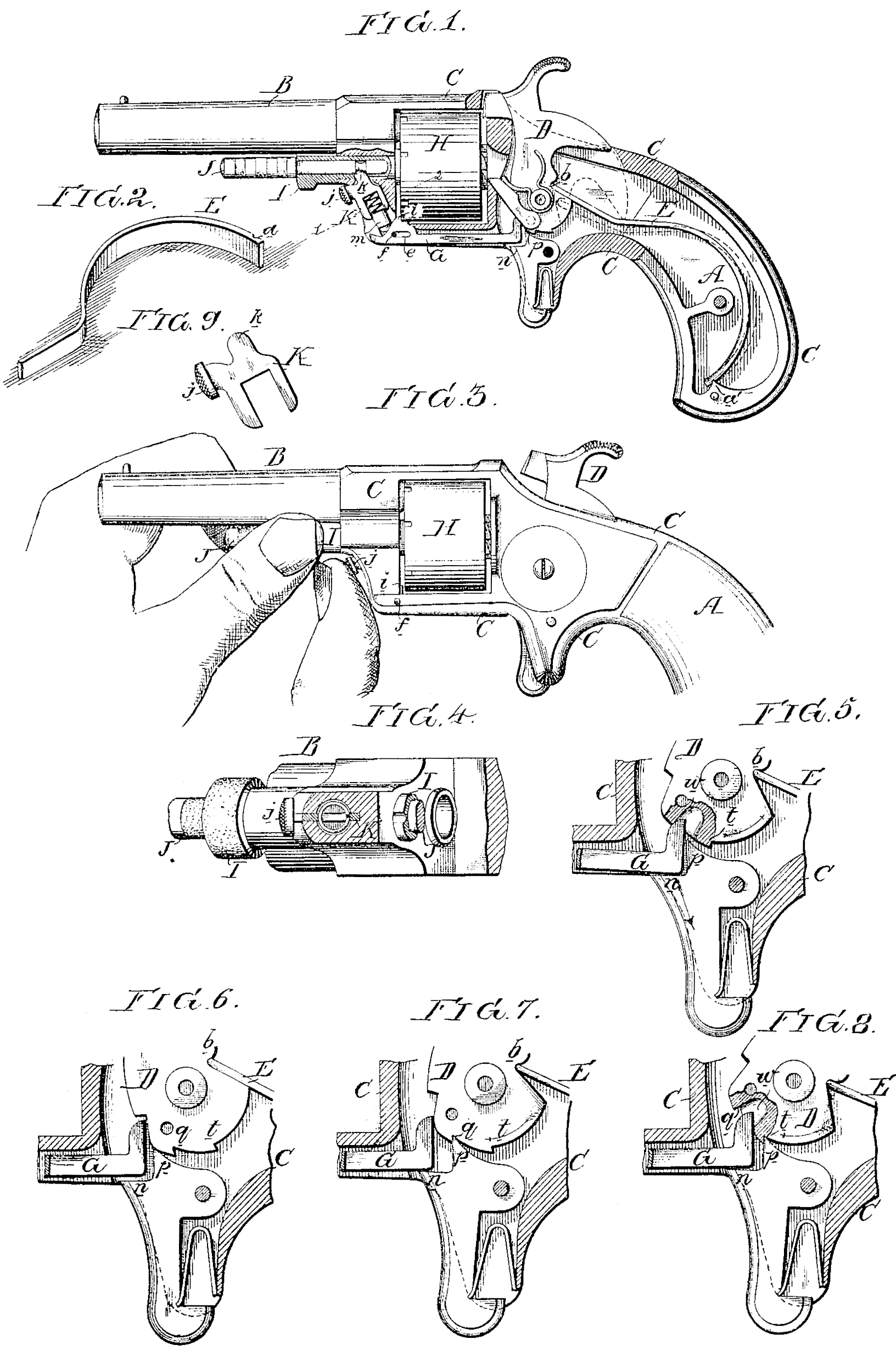
In the accompanying drawings, Figure 1,Sheet 1, is a side view of the fire-arm, partly in section; Fig. 2, a perspective view of the improved mainspring; Fig. 3, a side view of the fire-arm, illustrating the mode of releasing the breech-pin; Fig. 4, an enlarged sectional view on the line 12, Fig. 1; Fig. 5, an enlarged view of part of Fig. 1, and illustrating, with Figs. 6, 7, and 8, the successive movements of the hammer and devices operating in conjunction there with.
A is the hollow stock of the revolver; B, the barrel; C, the frame, and D the hammer, which is hung upon a pin passing through the stock in the usual manner. The mainspring E, shown in Fig. 2, consists of a plain strip of steel bent to the form illustrated, and having at its wide end a simple notch, a, adapted to a pointed projection, a’, in the stock A, the outer and narrow end of the spring being adapted to a recess, b, at the rear of the hammer. The spring is introduced into its place by first fitting its outer end into the notch of the hammer, and then bending the spring until its notch a fits onto the projection a’ of the stock. In the recess or groove in the lower part of the frame is a lever, G, having an elongated opening, e, through which and through the frame passes a small pin, f, the lever having the usual projection i adapted to notches at the end of the cylinder H. The slot for containing the lever G is continued upward in front of the frame for receiving the retainer K, which consists of a simple plate adapted to and guided by the above-mentioned slot. This plate, an enlarged view of which is shown in Fig. 9, has a serrated knob, j, so situated as to be conveniently reached by the thumb of the right hand, as shown in Fig. 3. The plate or retainer has also a projection, k, Which passes through an opening in the tubular breech-pin I, and into an annular groove in the pin J, which fits snugly, but so as to slide freely, in the said tubular breech-pin.
It should be here understood that the projection k of the plate K does not prevent the inner pin J from being extracted. It merely serves to keep the said pin steady in its place, so that by a slight effort it can at any time be withdrawn from the tubular pin. The latter, however, is retained in its place by the projection k of the plate K until the latter is depressed by manipulating the knob j, but owing to a groove in the tubular breech-pin, which groove communicates with the opening for the reception of the said projection k, the breech-pin can be re-introduced into its place without any manipulation of the plate K. This plate is slotted for the reception of a spiral spring, and the end of a pin, m, which bears against the end of the lever G, the tendency of this spring being to maintain the plate K, as well as the lever, in the position shown in Fig. 1. The pin m is cylindrical, and is introduced into its place through a hole bored in the frame, as best observed in Fig. 4. The trigger is of the peculiar shape shown in Figs. 5, 6, 7, and 8. It has two projections, in and p, the latter being adapted to either of two notches, q or t, in the hammer. In Fig. 6 the hammer is down, the long arm of the lever G is elevated, and the cylinder H is retained by the said lever. In Fig. 7 the hammer has been moved to half-cock, the projection p of the trigger fitting into the notch q of the hammer, and the lever G has been moved forward by the hammer so as to release the cylinder, which can, consequently, be turned during the next movement of the hammer. When the hammer has very nearly reached the position of full-cock, a notch, w, is presented in the edge of the hammer for the reception of the turned-up end of the lever G, so that the latter will instantly move back and lock the cylinder, this locking taking place simultaneously, or nearly so, with the arrival of the hammer at full-cock. When the trigger is pulled so as to release the hammer, the edge of the notch w in the latter bears, against the turned-up end of the lever G, which bears on the projection in of the trigger, and thus prevents the projection p of the trigger from entering the notch q of the hammer.
I claim as my invention—
1. The retaining-plate K, adapted to a slot in the frame, and to the tubular breech-pin I, and combined with the spring-pin m and lever G, all substantially as set forth.
2. The combination described of the hammer, the lever G, and projection n of the trigger.
In testimony whereof I have signed my name to this specification in the presence of two subscribing witnesses.
JACOB RUPERTUS.
Witnesses:
Hubert Howson,
Harry Smith.