
US 161343
UNITED STATES PATENT OFFICE.
JOHN H. LESTER, OF NIANTIC, ASSIGNOR TO HIMSELF AND ELIAS F. MORGAN, OF NEW LONDON, CONNECTICUT.
IMPROVEMENT IN LOCKS FOR FIRE-ARMS.
Specification forming part of Letters Patent No. 162,343, dated March 30, 1875; application filed February 26, 1875.
To all whom it may concern:
Be it known that I, John H. Lester, of Niantic, East Lyme, New London county, Connecticut, have invented certain. Improvements relating to Fire-Arms, of which the following is a specification:
I have devised and successfully applied mechanism by which the cock or hammer of the lock is securely held to prevent accidental discharge. I prefer, usually, to thus hold the hammer in the cocked position; but I propose to provide means whereby it may be so held either cocked, half-cocked, or fully down.
My mechanism not only secures the cock, but also secures itself against accidental derangement. It can be liberated very quickly by proper movements, but the liberating movements are such as are virtually beyond danger of being effected by accident. It requires deliberate intention and considerable skill and force to liberate the hammer and put the lock in condition for firing.
The following is a description of what I consider the best means of carrying out the invention.
The accompanying drawings form a part of this specification.
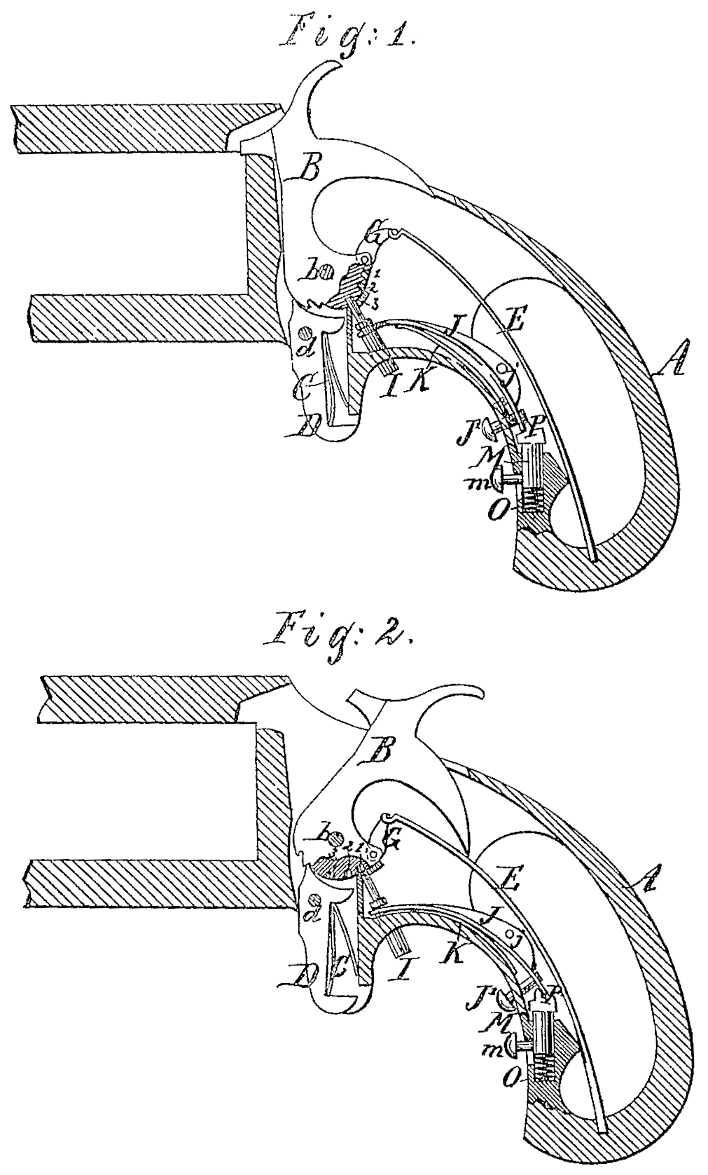
Figure 1 is a vertical longitudinal section through the lock and the immediately adjacent parts of a pistol. The form shown is that of an ordinary revolver; but the invention Will apply to any style of revolver, or breech-loader, or muzzle-loader, for military or Sporting purposes. It is intended to apply generally to all kinds and classes of fire-arms operating by a hammer. This figure shows the works with the hammer secured. These curing means is operated in the same position when the hammer is secured in the cocked or half-Cocked position. Fig. 2 represents the same parts in the liberated condition, ready for firing.
Similar letters of reference indicate like parts in both the figures.
A is the stock or frame. B is the hammer, turning on the center or stud b. D is the trigger, turning on the center d, and operated by the sear-spring C. E. is the mainspring, operating the hammer by a link, G. All these parts may be in the ordinary form and perform their ordinary functions. I is a locking-pin, standing in a position nearly radial to the stud b, but capable of moving toward and from such stud. It is strongly supported and guided in the framing A, and is adapted to match in holes 1,2,3 in the hammer B. When the hammer is at full cock, the hole 1 is presented in range with the locking pin I. When the hammer is at half-cock the second hole 2 is so presented, and when the hammer is fully down the third hole 3 is presented. In either position the thrusting of the pin I inward toward the axis b engages it in the corresponding hole, and secures the hammer against possible movement until the pin I is withdrawn. J is a bent lever, turning on the center j. One end takes hold of the pin I by engaging in a groove or between collars formed thereon. The other end carries a knob or stud, J’, which may be operated from the outside of the stock or handle. K is a spring, arranged as shown, and which tends to move the lever J so as to engage the pin I with the holes in the lever B. M is a safety-catch, capable of a little longitudinal motion, and driven upward by the coil-spring O, so that it tends to press always against the adjacent end of the lever J. A knife-edge, P, is formed on its upper end, which, in one position of the lever J, stands inside of the lever, and in the other position of the lever J stands outside thereof. In either position it secures the lever J against being moved by any force. This safety-catch M may be turned back, when required, by acting with the thumb-nail on the projection m, which extends out through a slot in the casing A.
In the ordinary handling and transportation of a pistol or other arm, the pin I should be engaged in one of the holes 1, 2, or 3, preferably in the hole 2, which corresponds to the half-cocked position of the hammer. With some arms the other Works of the lock are quite effective in holding the parts against being discharged in the half-cocked position. But all arms are liable, by wear or other cause, to become sufficiently deranged to be discharged at half-cock by any considerable blow or other disturbing force. My pin I is intended to insure absolute immunity against accidental discharge, except when the arm is intentionally put in condition for immediate firing by withdrawing the pin I.
In order to effect the operation of withdrawing the pin I the force of the fingers or other means must be applied to two different parts. First, the projection m must be pressed down ward sufficiently to overcome the friction and compress the spring O. Having thus withdrawn the safety-catch M, the fingers of the same or other hand may be applied to the projection or knob J’, pressing it inward with sufficient force to withdraw the pin I. So soon as the pin I is fully withdrawn from the hammer B the safety-slide M may be released, on which it rises and engages on the outside of the lever J, and thenceforward holds the pin I out of contact with the hammer B, and allows the pistol to be discharged in the usual manner. The pistol should be only kept in this dangerous condition until the emergency for which it was thus prepared is passed, when, by the reverse operation, the pin I should be again thrust into one of the holes in the hammer, and again secured there by the slide M, as at first.
I esteem it an advantage that the end of the pin I projects through the outside of the case, and is visible from the outside, because it shows or aids to show at a glance, or by feeling in the dark, whether the pistol is or is not in condition for firing. I can modify the form and proportions of some of the parts and correspondingly modify the operation. Thus, for example, some may prefer to dispense with the locking-slide M, and allow the lever J to be Operated more easily. Others may prefer to partially dispense with it by filling up one side of the ridge on its upper end, so that while it is effective in holding the pin I back or Out of engagement with the hammer it is of no effect in holding it into engagement. Either of these last modifications will allow the arm to be more easily put in condition for firing, but it involves obviously an increased risk that the pin or equivalent safety locking means I shall be moved into an unlocked position by an accidental blow, and thus be rendered ineffective to the danger of the user or his companions. Certain features of the invention may be used with some benefit with out the others, but I prefer to use the whole in combination.
I claim as my invention—
1. A fire-arm having the pin or locking means I, in combination with the hammer B, having two or more recesses, 123, and adapted to serve therewith in locking the hammer in several different positions, as and for the purposes herein specified.
2. In combination with the trigger D d and the usual provision for cocking, retaining, and liberating the hammer by the trigger, the employment of one or more separate recesses, 1 2 3, in the hammer, in combination with a locking-piece, I, and spring K, acting through suitable connections to constantly throw the locking-piece into engagement with the recesses, as and for the purposes specified.
3. The safety-catch M m, serving in combination with the hammer B, locking-piece, and with suitable connecting and operating means to further insure against accident, as herein specified.
In testimony whereof I have hereunto set my hand this 23d day of February, 1875, in the presence of two subscribing witnesses.
JOHN B. LESTER.
Witnesses:
Aug, Brandegee,
Robert Palmer.