
US 23711
UNITED STATES PATENT OFFICE.
JACOB RUPERTUS, OF PHILADELPHIA, PENNSYLVANIA.
IMPROVEMENT IN REVOVING FIRE-ARMS.
Specification forming part of Letters Patent No. 23,711, dated April 19, 1859.
To all whom it may concern:
Be it known that I, Jacob Rupertus, of the city of Philadelphia, in the county of Philadelphia and State of Pennsylvania, have invented certain new and useful Improvements in that class of Fire-Arms known as “Revolvers;” and I do hereby declare that the following is a full, clear, and exact description of the same, reference being had to the accompanying drawings, forming part of this specification, in which—
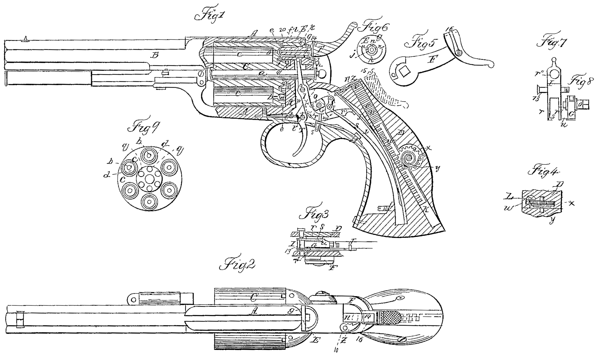
Figure 1 is a longitudinal section of a pistol with my improvements. Fig. 2 is a top view of the same. Fig. 3 is a section of the lock, exhibiting its parts as they would be seen from the under side, with the trigger removed. Fig. 4 is a section of the self-acting priming apparatus. Fig. 5 is a side view of the hammer. Fig. 6 is a back view of what I term the “safety tube.” Figs. 7 and 8 are back views of parts of the lock, exhibiting them detached. Fig. 9 is a back view of the cylinder.
Similar letters of reference indicate corresponding parts in the several figures.
My invention relates to that description of revolving fire-arms which have the many chambered cylinder rotating on an axis parallel with the bore of the barrel.
It consists in what I term a “safety-tube,” which serves to convey the fire from the priming to the several chambers, to prevent any escape of the fire in a lateral direction from the vent of one chamber to that of the next, and consequent accidental discharge of any of the chambers, and to lock the cylinder with its chambers in line with the barrel.
It also consists in certain means whereby the necessary movements of the aforesaid safety-tube are effected by the movements of the hammer.
To enable others to make and use my invention, I will proceed to describe its construction and operation.
A is the cylinder-frame, which contains the many-chambered cylinder C, and is extended rearward, as shown at D, to constitute the principal portion of the stock.
B is the barrel, which may be made in one piece with the frame A or screwed thereunto.
a is the pin on which the cylinder C rotates, inserted through the back of the frame A. The cylinder C has the vents b b of its several chambers c e made directly through the center of the breech or back of the cylinder, and each vent is countersunk from the back of the cylinder, as shown at d in Figs. 1 and 9, to receive the front of the central portion, 20, of the safety-tube E; and concentric with each countersunk recess d there is a circular groove, e, formed in the back of the cylinder, to receive the outer portion, f, of the safety-tube E. The safety-tube E is made externally of cylindrical form, with a flange, g, round its rear and a nipple-like projection, j, on the center thereof, and with a lip or bib, h, extended rearward from the flange g at the bottom. It has a small hole, k, drilled directly through its center, and has a deep concentric circular groove, l, cut in from its front extremity and a shallower corresponding groove, m, at the rear end, and these two grooves l and m have communication pro vided between them by means of small holes n n. The said tube is fitted to slide freely back and forth a limited distance through a circular opening in the back of the frame A, said circular opening in the back of the frame being so situated that the vents of the several chambers, being arranged in a circle described from the center of the cylinder, may be successively brought to a position directly opposite the center of the said tube. The front of the external portion, f, of the said tube, which surrounds the groove l, is made to fit the circular grooves e e in the back of the cylinder, so that it may not only lock the cylinder very securely with either of its chambers in line with the barrel, but that it at the same time constitutes an effective shield to prevent any fire escaping laterally from the vent of the said chamber when the explosion of its charge takes place. The front extremity of the central portion of the said tube, which is within the groove l, is formed to enter the countersunk recesses d d of the cylinder, to convey the fire from the priming which is exploded against the nipple j to the vents of the cylinder to fire the charges; but the said portion of the tube does not fit the said recesses so tightly as to prevent the escape of the smoke and gases from the chambers through the vents, but fits loosely enough, as shown in Fig. 1, to permit them to escape from the vents around the sides of the cavities did and through the circular groove l, holes n n, and groove m of the tube.
F is the hammer, working upon the usual arbor, o, and G is the tumbler, secured, as usual, to the same arbor.
T is the trigger, and t the trigger-spring.
S is the mainspring.
p is the dog, attached to the hammer to operate upon the projections q q on the back of the cylinder, for the purpose of rotating the same.
I is a forked lever, through which the tumbler operates upon the safety-tube E to make it lock and unlock the cylinder and cover and uncover the vents of the chambers. This lever, of which Fig. 7 is a back view, works on a fulcrum-pin, 13, which occupies a fixed position in the back of the frame A, some distance above and in front of and parallel with the hammer-arbor o, and its prongs r r’ extend downward and rearward, one on each side of the tumbler, one, r, terminating at the side of the tumbler, and the other, r”, being extended some distance in rear thereof to hook onto a spring, J, which tends to raise it and so to throw forward the upper extremity of the lever, which is made to engage permanently with the safety-tube by being rounded off to enter a small cavity provided for it in the under side of the said tube. The prong r is made elastic in a lateral direction, and is provided on its inner side, close to its extremity, with a small tooth, s, which is beveled on its front side, as shown in Fig. 3, the said tooth being intended to be engaged by a tooth, u, on the corresponding side of the tumbler for the purpose of enabling the tumbler during the cocking movement to drive forward the prong r, and so draw back the upper end of the lever I and draw back the safety-tube to permit the rotary motion of the cylinder. The safety-tube should be drawn back far enough to free the cylinder before the lock arrives at half-cock, to permit the cylinder to be turned by hand when the lock is at half-cock. The tooth u, on the tumbler is beveled in the opposite direction to the tooth s of the lever I, as shown in Fig. 3, and the said teeth are of such width that just as or slightly before the cocking movement is completed the tooth s, whose movement in cocking is downward, while that of at is for the most part upward, Works clear of the latter tooth, and thus leaves the lever I free from the tumbler and entirely under the influence of the spring J, and, this taking place just as the rotary movement of the cylinder is completed, the said spring forces forward the safety-tube into the groove e and cavity d belonging to that chamber which arrives in front of the barrel, and so locks the cylinder and covers the vent in such manner as to prevent the escape of fire or gases in a lateral direction. The bevels on the teeth s u (exhibited in Fig. 3) enable the former to pass the latter as the hammer moves forward when let off, the flexibility of the elastic prong r being sufficient to permit it to be moved aside as the tooth u passes the tooth s. The lever I has a hole, r”, through it to permit the pin a to pass through it.
K is a cylindrical cavity drilled or otherwise formed in the stock to constitute a magazine for the percussion priming, which I prefer to use in lozenge-like caps v v for the sake of getting in sufficient for as great a number of discharges as possible. This magazine is fitted with a piston-like follower, L, to force up the caps. The said piston is cut away to form a toothed rack, w, on one side, to gear with a pinion, x, arranged to work on fixed bearings within the stock, and a convolute spring, y, is applied in such a manner as to turn this pinion in a direction to drive up the follower L as fast as permitted by the removal of the caps one by one from the the top of the pile within the magazine. By the use of the convolute spring and the rack and pinion for the purpose of operating the follower L, instead of a simple spiral spring, a more nearly uniform upward pressure on the follower is obtained. The magazine is closed at the top by a cover, z, which is capable of being swung open on a pin, 10, for the purpose of filling the magazine. This cover is represented partly broken off in Fig. 2 to expose the parts below. Close with in this cover & there is fitted a slide, 11, whose duty it is to push the caps out one by one through a suitable slot, 15, in the back part of the magazine, into a cavity, 14, formed in the face of the hammer to receive them, the hammer, when cocked, lying back with its face in a proper position close behind the mouth of the magazine, as shown in Fig. 2, and also shown by the red outlines in Fig. 1. The slide 11 is attached to the spring J and worked by the combined operations of the lever I and the spring J in the following manner: When during the cocking movement the tooth u of the tumbler G, by its action on the tooth s of the lever I, forces forward the lower portion or fork of said lever, the prong r’ carries forward the spring J along with it and causes the said spring to draw forward the slide 11 entirely off the mouth of the magazine, and thus permits the spring y to force up the follower L and feed up the caps v v till the top one is in close contact with the cover z; but when the lever I is liberated from the tumbler, as the cocking movement is completed, as already described, the spring J is allowed to return and push back the slide 11, which, being of a thickness about equal to the depth of the caps, forces out the top cap through the slots 15 into the cavity 14 in the face of the hammer, where it is retained for any desirable length of time by the pressure of a small spring, 16, which is attached to one side of the hammer-head, and enters the said cavity through a slot in the side of the head. When the hammer is let off it carries the cap forward against the nipple and explodes it.
What I claim as my invention, and desire to secure by Letters Patent, is—
1. The safety-tube E, constructed, applied, and operating substantially as and for the several purposes herein specified.
2. Producing the necessary movements of the safety-tube E by means of a forked or toothed lever, I, a spring, J, or its equivalent, and a tooth, u, on the tumbler, the whole being applied and operating substantially as herein described.
JACOB RUPERTUS.
Witnesses:
Charles D. Freeman,
William. H. Dingler.