
US 23861
UNITED STATES PATENT OFFICE.
JOSEPH RIDER, OF NEWARK, OHIO.
IMPROVEMENT IN REVOVING FIRE-ARMS.
Specification forming part of Letters Patent No. 23,861, dated May 3, 1859.
To all whom it may concern:
Be it known that I, Joseph Rider, of Newark, in the county of Licking and State of Ohio, have invented certain new and useful improvements in that class of fire-arms known as “Revolvers;” and I do hereby declare that the following is a full, clear, and exact description of the same, reference being had to the annexed drawings, making a part of this specification, in which—
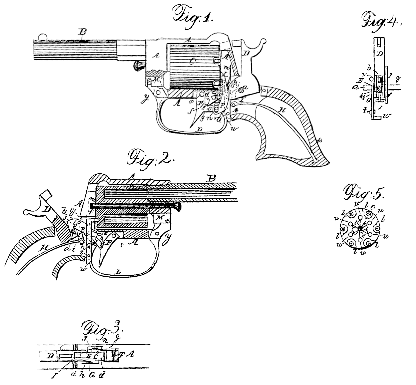
Figure 1 is a side view of a pistol with my improvements, representing it with one side of the stock removed to expose the lock. Fig. 2 is a longitudinal central section of the same. Fig. 3 is a horizontal section of the lock. Fig. 4 is a transverse section of the same. Fig. 5 is a back view of the cylinder.
Similar letters of reference indicate corresponding parts in the several figures.
My invention relates to that kind of revolver which is in most common use— viz., that having a fixed barrel and a chambered cylinder rotating on an axis parallel with the bore of the barrel.
My invention consists in a certain novel simple construction and mode of applying and combining the several parts of the lock of a revolver, whereby they are made capable of operation in a very effective and certain manner, either by the trigger alone for very rapidly-repeated firing, or by the cocking of the hammer and firing only by the trigger for firing more deliberately and with more accurate aim.
It also consists in so constructing the trigger-guard as to serve as a spring for operating the device which locks the cylinder during the act of firing, as a lever for operating the rammer, and as a spring for locking itself in place as the trigger-guard.
To enable others skilled in the art to make and use my invention, I will proceed to describe its construction and operation.
A is the metal frame, whose front part contains the rotating chambered cylinder C, and has secured to it the barrel B, and whose back part constitutes the principal portion of the stock and contains the lock, by which term I mean to include the hammer and trigger and all the mechanism through Whose agency the cocking and letting off the hammer, the rotation, and the locking and unlocking of the cylinder are effected.
D is the hammer, which is arranged in the usual manner to Work on a fixed pin, a, but which, instead of having the usual notches to be engaged by a sear for holding it cocked, or at half-cock, is mortised perpendicularly to the arbor to receive within it a portion of a dog, E, which I will term the “cocking-dog,” Which is attached to the hammer in front of the pin a by a pin, b, and Which has on its upper side two ratchet-like notches, c and d, to engage with a stationary stop, e, which is properly arranged within the frame A, the first notch, c, engaging with the said stop to hold the hammer at half-cock, and the second, d, engaging with it to hold the hammer at full-cock when the hammer is drawn back, pulling directly upon it. The said cocking-dog has also a notch, f, in its extremity for the purpose of receiving a tooth, g, which is formed on the trigger F, (see Fig. 1) and which enters the said notch for the purposes of effecting the operations of the hammer and cylinder through the sole agency of the trigger for rapidly-repeated firing, as will be hereinafter described. The said cocking-dog has also on one side a long thin tooth, h, whose duty is to operate on a tooth, i, attached to a locking-lever, G, for the purpose of unlocking the cylinder from the said lever G to permit the cylinder to be rotated by the act of cocking the hammer.
H is the mainspring, which, instead of being connected with the hammer either directly or by a stirrup, is connected by a stirrup, I, with the cocking-dog E, said stirrup being attached to the said dog by a pin, j, arranged just in rear of the pin b, which attaches the said dog to the hammer, and between the latter pin and the main pin a of the hammer. The spring thus applied exerts its force to throw forward the hammer, and also to hold up the front portion of the cocking-dog, which it always tends to keep in contact with the stop e.
To equalize, as far as possible, the power exerted by the spring on the hammer throughout the whole movement of the hammer, I provide a notch, z, in the stationary pin a on which the hammer works, said notch being cut about halfway through said pin in order that when the hammer is at full-cock and the spring subject to its greatest degree of strain the stirrup I, by entering the said notch, as shown in Fig. 2, may pull as nearly as practicable in a direct line between the point of attachment of the spring and the center of motion of the hammer.
J is the rotating dog, which is in some respects like the dog commonly employed to effect the rotation of the cylinder by the act of cocking the hammer, and operates in a similar manner in a series of notches, l l, in the back of the cylinder. This dog J lies loosely in a place provided for it within the frame A, between the hammer and the side of the stock, which confine it as far necessary in a lateral direction, and it is kept from slipping downward or backward out of its place partly by a spring, m, attached to its back, which rests against the back of the cavity in the frame A, and partly by a pin, n, attached to the heel o of the trigger, said pin entering a slot, p, in the said dog J.
The said dog J has a projection, q, on one side, which is always above a horn, r, on the front part of the hammer butt or tumbler, and by the action of the said horn r on the said projection q the said dog is caused to rise and rotate the cylinder when the hammer is drawn back by hand to cock it.
When the operations of raising the hammer, revolving the cylinder, and firing are performed Solely by the act of pulling the trigger, the dog J is operated by the pin n, attached to the trigger, the said pin moving up in the slot p during the first part of the movement of the trigger to afford opportunity for the ratchet-notch d of the cocking-dog to be thrown clear of the stop e, and then coming in contact with the top of the said slot p and forcing up the dog J to produce the rotation of the cylinder. The cylinder is prevented being carried too far by the said rotating dog J, having the portion above the slot p so formed, as shown at 8 in Figs. 1 and 2, as to enter notches f f in the rear portion of the periphery of the cylinder to stop it as the movement of the dog ceases.
The trigger F is differently formed from the triggers of all or most other fire-arms, having its heel o some distance lower than the pin s, which constitutes its center of motion, the said heel being only just wide enough to give it strength to carry the pin n, and at the side of this heel is the tooth g, which serves the purpose of letting of the hammer to fire the piece at all times, and also serves the purpose of engaging in the notch f of the cocking-dog E to raise or throw back the hammer when the entire operation of the piece is effected through the agency of the trigger. In the last-mentioned operation, when the trigger is pulled back, the said tooth first strikes the lower side of the notch f, and so depresses the cocking dog so far that it is entirely clear of the stop e, and its point or edge then entering into the angle of the said notch holds the cocking-dog E steady and clear of the stop e, while it forces the said dog back and forces back the hammer, which continues to move back till the tooth g works out of the notch on the upper side of the latter, and so liberates the dog and the hammer and leaves them both under the uncontrolled influence of the mainspring which forces forward the hammer. As the hammer falls and the dog E comes forward the said dog is caused to slide down the back of the trigger below the tooth g, and so prevented coming in contact with the stop e till the trigger is liberated and allowed to be moved forward by the pressure of the same dog produced by the mainspring, which spring, causing the said dog always to press forward against the trigger, renders a separate trigger-spring unnecessary. The trigger in being thrown for ward pulls down the rotating dog. When the trigger is only used to let off the hammer after the latter has been cocked the back of the tooth g acts upon the lower edge of the front extremity of the cocking-dog, and so forces down the said dog clear of the stop e, and when thus forced down the upper edge of the rear extremity of the dog passes the tooth g without catching it, and slides down the rear of the trigger, as before described, and during this operation of the trigger the pin n moves in the slot p without moving the dog J.
The locking-lever G works on a fulcrum-pin, t, which is arranged very near the bottom of the frame A and behind the cylinder, and also very near the bottom of the said lever. The said lever has its upper end bent forward in the form of a bolt, as shown at v, Fig. 2, to enter either one of a series of holes, u, u, (see Fig. 5,) in the back of the cylinder, to lock it with its chambers in line with the barrel at the time of firing, and it has a hook, w, on one side of its lower end to engage with a latch-like tooth, x, on the rear end of the trigger-guard L, which is made to constitute at the same time a lever working on a fulcrum, y, in the front of the frame A for operating the ball-rammer M, and also serves as a spring to force back the lower end of the lever G and force forward its bolt v. By making the guard constitute a lever, and that lever light and elastic enough to constitute a spring, and with a latch, x, at the end, such lever is made to secure itself in position in which it constitutes the guard, beside serving to throw the locking lever into action. The trigger-guard is unfastened from the hook w of the locking-lever to operate the rammer by pressing forward its rear end far enough to liberate the latch-like tooth x. The bolt of the locking-lever G is withdrawn from the holes u u in the cylinder by the action of the before-mentioned thin tooth h of the cocking-dog upon the tooth i, attached to the side of the locking-lever. The back edge of said tooth h, as the cocking-dog commences to move back with the hammer, presses against the tooth i, and so forces back the upper part of the lever G and draws its bolt from the cylinder, but owing to the thinness of the said tooth h its edge soon passes and its lower face arrives in contact with the tooth i, and so, though it then ceases to push the said tooth i farther back, continues to hold it till its front edge passes the said tooth and lets the lever G escape. The bolt v then continues in contact with the back of the cylinder C until, as the action of the rotating dog J ceases, a hole u arrives opposite to the said bolt for it to drop into and lock the cylinder for the next fire.
What I claim as my invention, and desire to secure by Letters Patent, is—
1. The cocking-dog E, with its notches c d, applied, in combination with the hammer and trigger and with a stationary stop, e, to operate, substantially as herein set forth, to effect the cocking of the hammer and firing.
2. In combination with the above, providing the said cocking-dog with a notch, f, in its extremity to be operated upon by a tooth, g, on the trigger, substantially as described, to operate the piece entirely by the trigger for rapidly-repeated firing without cocking.
3. Combining the locking-lever G with the cocking-dog E by means of a tooth, i, upon the lever and a tooth, h, upon the dog, the teeth being formed to operate substantially as herein specified.
4. The construction and application of the trigger-guard, in combination with the locking-levers, to serve three purposes— viz., as the guard, as the lever for operating the rammer, and as the spring for operating the locking-lever or its equivalent— substantially as herein described.
JOSEPH RIDER.
Witnesses:
Jas. R. Stanbery,
James White.