
US 353914
UNITED STATES PATENT OFFICE.
JAMES BOLAND, OF NORWICH, CONNECTICUT.
REVOLVER.
SPECIFICATION forming part of Letters Patent No. 353,914, dated December 7, 1886.
Application filed July 30, 1886. Serial No. 209,520. (No model.)
To all whom it may concern:
Be it known that I, James Boland, a citizen Of the United States, residing at Norwich, New London county, Connecticut, have invented a certain new and useful Improvement in Revolving Fire-Arms, which improvement is fully set forth and described in the following Specification, reference being had to the accompanying drawings.
My invention is in that class of revolving arms which have the barrel and frame sections hinged together, the several parts being SO constructed and connected that the movement of the barrel as it swings forward forces the cartridge-ejector outward until the empty Shells drop from the cylinder. Said ejecting mechanism is then automatically released and returned to its closed position within the cylinder ready for reloading.
It is my purpose to improve the particular device which retains, the so-called “lifter” or “idler” in a fixed position as the barrel is swung forward.
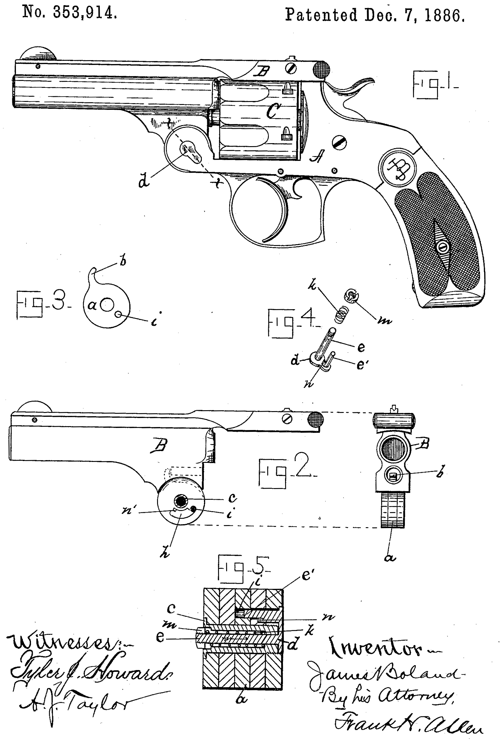
Referring to the drawings hereunto annexed, Figure 1 is a side view of a revolver having Said improved device attached thereto. Fig. 2 shows side and rear views of the barrel detached. Fig. 3 is a detached view of the lifter a. Fig. 4 is a perspective view of the pawl, spring, and nut, which form the essential elements of my improvement. Fig. 5 is a cross-section, considerably enlarged, of the hinge-joint, taken on line x x of Fig. 1.
The letter A indicates the frame of the arm, and B the barrel, each provided with hinge-leaves and connected forward of the cylinder, as illustrated in Fig. 1. Within the cylinder usual stem extending into the barrel and held forward normally by a spiral spring; but as these devices are well known in this class of arms, I have thought it unnecessary to show detailed drawings of them here. The barrel-hinge is formed preferably with two leaves, which enter between corresponding leaves on the frame A, said barrel-leaves being separated a distance sufficient to receive the lifter a. This lifter is provided with an integral or fixed horn, b, to engage the end of the ejector-stem. The barrel, frame, and lifter, after being properly assembled, are held in place by a counterbored screw, c, which forms the hinge-pivot.
Having brought the arm to the-construction described, it becomes necessary to provide a device which will lock together the frame and lifter, so that, as the barrel is swung forward, said lifter will check the ejector and cause it to throw out the empty shells. To do this I have provided a plate or disk, d, having two integral studs or projections, e e’, the former of which passes through the counterbored screw c, the latter reaching through a slot, h, in one leaf of the barrel, to engage a hole, i, in the lifter. Within the counterbored screw I place a spiral spring, k, and then screw a nut, m, onto the stud e, the spring acting with a constant tendency to hold disk d within its seat in the hinge, and to force stud e’ forward into the lifter-hole i. (See Fig. 5.)
In order to automatically release the stud e’ (which is practically a pawl) from the lifter-hole, I have formed an inclined or wedge-shaped projection, n, between studs e and e’, and a corresponding projection, n’, in the end of slot h. As the barrel swings forward, the incline n’ gradually approaches the incline n, and at the proper instant engages and forces it outward, thus withdrawing stud e’ from the lifter and allowing it (the lifter) to snap forward with the ejector-stem. As the barrel is swung rearward after loading to lock with the frame, spring k again brings stud e’ into engagement with the lifter-hole i. When it is desired to open the arm without ejecting the cartridges, suitable pressure of a finger on nut m will throw stud e’ out of engagement with the lifter, said nut being within convenient reach of the forefinger of the left hand as the barrel is grasped in the customary and natural manner. In this respect my improved device is much more convenient than many of the partially-concealed pawls and latches heretofore used, and the form of my device is such that it may be easily and cheaply produced and assembled.
My device may be used without the inclined surfaces n and n’, in which case the lifter is released at the proper time by pressure on nut m; but I consider the construction here shown far preferable, as it works automatically.
Having thus described my invention, I claim as new and wish to secure by Letters Patent—
1. In combination with a frame and barrel, hinged as described, and a lifter located between the hinge-leaves of the barrel, a pivot-screw drilled centrally throughout its entire length, adapted to pass through said frame, barrel, and lifter to interlock said parts, the longitudinally-movable spring-pressed stud e, passing through said pivot-screw, having a plate, d, extending a considerable distance outward from the center of the hinge, and formed with stud e’ parallel with stud e, and of such length that it may reach inward through the barrel-hinge to engage a perforation, i, in the said lifter, as herein described, and for the object specified.
2. In a revolver of the class referred to, in combination with the frame and a barrel having slot h and cam n’, a lifter having the perforation i, coincident with said barrel-slot, a pivot-screw drilled through its entire length, and a spring-pressed plug located within said screw having the radial disk or arm d extending a considerable distance outward from the hinge-center, and carrying at its outer end the stud e’, and cam n, adapted to engage, respectively, the said perforation i and barrel-cam n’, as herein described, and for the object set forth.
JAMES BOLAND.
Witnesses:
Frank. H. Allen,
Tyler. J. Howard.