
US 350346
UNITED STATES PATENT OFFICE.
GEORGE W. CILLEY, OF NORWICH, CONNECTICUT, ASSIGNOR TO THE HOPKINS & ALLEN MANUFACTURING COMPANY, OF SAME PLACE.
REVOLVER.
SPECIFICATION forming part of Letters Patent No. 350,346, dated October 5, 1886.
Application filed July 1, 1 SSG. Serial No. 206,845. (No model.)
To all whom it may concern:
Be it known that I, George W. Cilley, a citizen of the United States, residing at Norwich, New London county, Connecticut, have invented a certain new and useful Improvement in Revolving Fire-Arms, which improvement is fully set forth and described in the following specification, reference being had to the accompanying drawings.
My improvement is in that class of revolvers in which the barrel and flame sections are hinged together forward of the cylinder, the several parts being so constructed and connected that the act of “breaking down” the barrel acts to force the ejector forward until the empty shells are expelled, when said ejector returns to its normal position in the cylinder. A familiar type of said class may be seen in Patent No. 227,481, issued to J. H. Bullard, May 11, 1880, to which patent I refer for a more detailed description of the features which are common to this class.
My object in this present invention is to provide a new form of spring, (for use in that sub-class which has a laterally-movable lifter or idler,) which spring may be easily and cheaply made, and which will be less liable to be displaced or broken by severe use.
In order to more clearly describe my invention, I have annexed hereunto a sheet of drawings, in which—
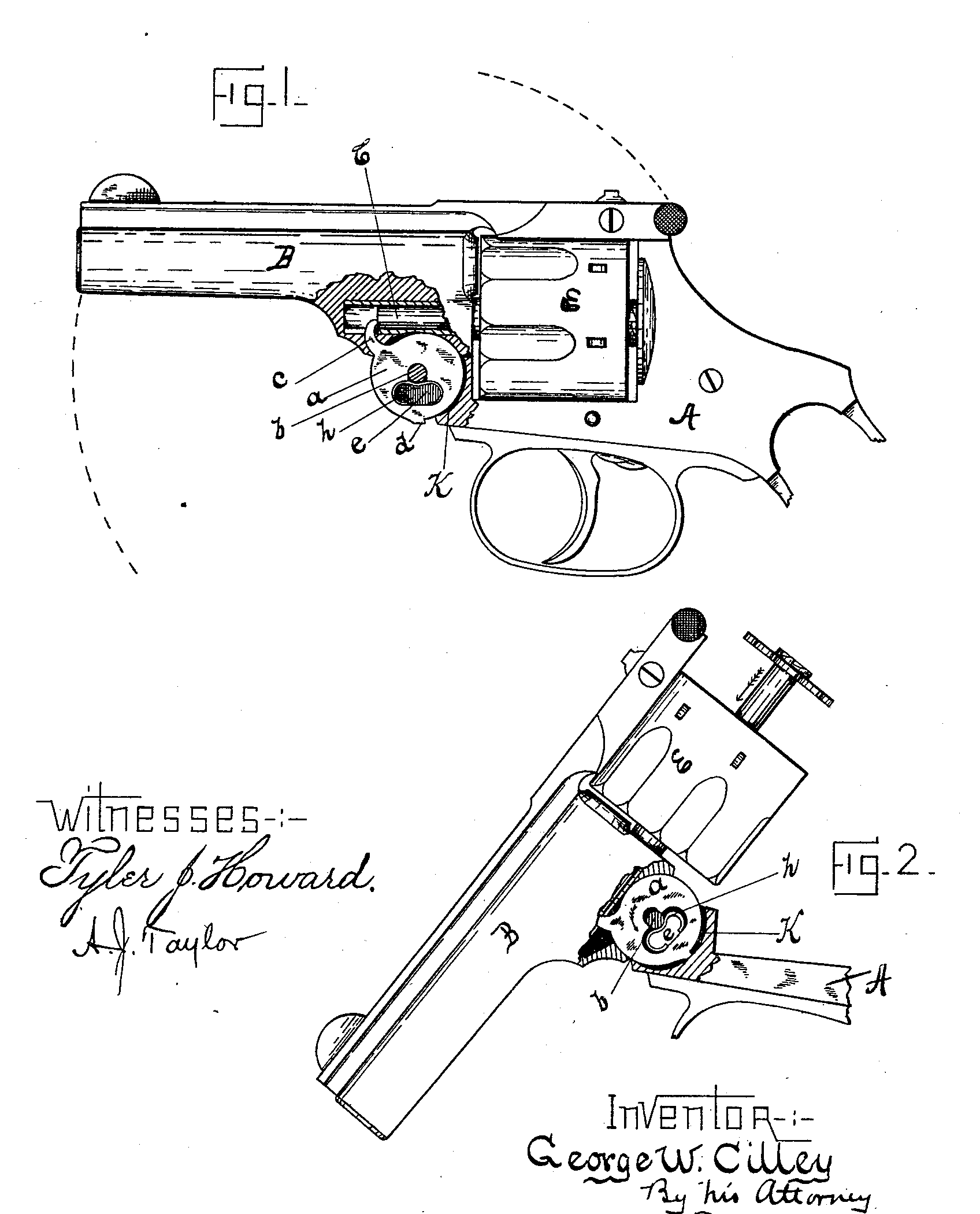
Figure 1 is a side elevation of a revolver having my improvement attached, a portion of the barrel and frame being cut away to expose the lifter and ejector-pin. Fig. 2 shows a portion of the frame with barrel thrown down, the lifter having been “tripped” by the barrel. The ejector is shown as in the act of returning to its normal position within the cylinder.
The letter A indicates a frame of ordinary construction, and B a barrel hinged thereto.
C represents the ejector stem, held forward by a retractor-spring concealed within the cylinder E.
My lifter or so-called “idler a is hung on the pivotal screw or stud b, and is provided with the usual hook, c, to engage the end of the ejector-stem; also a projection, d, to engage the frame while in the act of ejecting. Said lifter is cut through at a point between the projection d and the pivot b, as shown at e, the recess thus formed leading into the pivot-hole a considerable distance below the center of said hole.
I have found it both convenient and cheap to drill two holes of suitable size for the ends of the desired slot or recess, and then to broach or punch out the uncut portions, leaving a clean recess With semicircular ends. In the recess so formed I place a spring, h, formed preferably of flattened steel, whose ends are bent to conform to the shape of recess e, and whose upper central portion bears with considerable force against stud b, with a tendency to draw the lifter downward, and thus hold the projection d in engagement with the frame.
When the barrel is tilted to eject the empty shells, the lifter remains in its normal position (shown in Fig. 1) until the barrel engages projection d and crowds the lifter upward against the force of spring h. The retractor-spring then returns the ejector to its closed position in the cylinder, and the arm is ready for reloading. As the barrel is swung forward to lock with the frame, spring h snaps the lifter-projection d back to its position in front of the frame.
I am aware that laterally-movable lifters have been shown and described heretofore; and I do not therefore seek to cover, broadly, such a device. So far as I am acquainted with the state of the art, lifters of this class have been held in and returned to their normal positions cither by a peripheral spring or by a spiral spring acting on an intermediate shoe which bears on the lifter-pivot. In the latter case the shoe is provided as an anti-frictional bearing to prevent the cramping or deflecting which would occur if the spiral spring rested against the stud b. My single spring avoids the added expense of such a shoe, and being concealed and held within the hinge-joint cannot work out of place.
In order to reduce the friction as the lifter-projection d is rotated within the frame, I have recessed said frame, as at K.
Having thus described my invention, I claim—
In an arm of the class referred to, in combination with the ejector -stem, a laterally-movable lifter provided with a recess, e, leading into the pivot-hole, as described, and a bow-spring (conforming in shape with the said recess) whose central portion engages the lifter-pivot, substantially as and for the object specified.
GEORGE W. CILLEY.
Witnesses:
Frank H. Allen,
John E. Warner.