
US 350367
UNITED STATES PATENT OFFICE.
CHARLES W. HOPKINS, OF NORWICH, CONNECTICUT.
REVOLVER.
SPECIFICATION forming part of Letters Patent No. 350,367, dated October 5, 1886.
Application filed July 1, 1886. Serial No. 206,849. (No model.)
To all whom it may concern:
Be it known that I, Charles W. Hopkins, a citizen of the United States, residing in the city of Norwich, county of New London, and State of Connecticut, have invented a certain new and useful Improvement in Revolving Fire-Arms, which improvement is fully set forth and described in the following specification, reference being had to the accompanying drawings, in which—
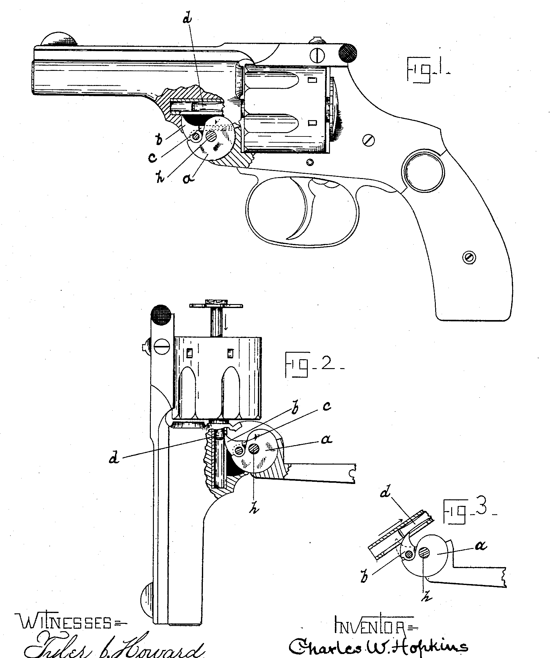
Figure 1 is a side view of a revolver of my new construction, shown partly in section and with barrel closed. Fig. 2 shows the barrel and the frame-strap to which said barrel is hinged. In said Fig. 2 the barrel is in its open position, the ejector-rod being shown as in the act of leaving the lifter to allow the ejector to return to its normal position for reloading. In Fig. 3 I have illustrated the relative positions of the lifter pawl and the ejector-rod as the barrel is being swung forward to lock with the frame.
My invention consists of an improved device for checking the ejector-rod in that class of revolvers which have their barrel and frame sections joined by a hinge at the front of the cylinder, and in which the operation of swinging the barrel forward acts to force the empty cartridge-cases out of the cylinder.
My object is to provide a device for operating the ejector-rod which shall be simple and strong, and which will enable me to construct the hinge-connection between the barrel and frame with less expense than heretofore.
The construction of the barrel and cylinder and of the ejecting mechanism contained therein is substantially of the form used in the so-called “Smith & Wesson Revolver,” and needs no detailed description.
There have been described and used heretofore various devices for checking the ejector-rod as the barrel is swung forward, such devices, so far as I am familiar with them, being formed either as pinions or as disks having a horn to engage said rod. Said devices are held in a given position by the frame until the cartridges are ejected, and are then released and caused to rotate on their pivots to allow the ejector to return to its seat within the cylinder. In all such forms the hinge must be split to receive said disks, either weakening the hinge or making it thicker than would otherwise be required.
In my newly-invented device I dispense with a rotatable disk and form my hinge of three leaves or sections, one of which, a, is a rigid part of the frame, the two others being integral parts of the barrel and adapted to straddle the frame-section. In the front edge of section a, I pivot a pawl, b, having a shoulder which engages the frame, to limit the outward movement of said pawl, and within said frame-section a, I place a spring-pressed plug, c, which engages the inner side of the pawl, and acts with a constant tendency to throw the free end of said pawl outward. The length of the pawl is such that it reaches upward into the arc which the end of the ejector-rod describes as the barrel is swung forward, and it will now be understood that as the barrel moves on its hinge-pivot h the ejector-rod (represented by the letter d) will engage pawl b and stop, while the barrel continues its movement, thus forcing the ejector out of the cylinder, as shown in Fig. 2.
In order that the ejector may be released from the pawl b and the ejector allowed to return to the cylinder for reloading while the barrel is open, I have so constructed and located the ejector-rod and pawl relative to each other that the circle traversed by the end of said rod in its extended position is enough larger than that in which it begins to travel that it (the rod) leaves the pawl and is free to return to its closed position within the cylinder. In other words, the engaging end of the ejector-rod, instead of traveling in an arc of a true circle as the barrel swings on the hinge, travels in a gradually-increasing circle, and at the proper time passes beyond the reach of the pawl b, and is forced forward to its closed position within the barrel by a retractor-spring of ordinary construction concealed in the cylinder.
In Fig. 2 the rod d is shown as having left the pawl and as moving toward its normal closed position. As the barrel is swung forward to lock with the frame the rod d presses the pawl inward (see Fig. 3) against the force of plug c until said rod passes the end of the pawl, when said pawl springs to its place in the rear of the rod, ready to again engage the end of said rod.
Having described my invention, I claim—
In an arm of the kind referred to, in combination with a frame having a rigid hinge-leaf with a spring-pressed pawl pivoted therein, substantially as described, a barrel formed with companion leaves adapted to engage said frame-section, and a longitudinally-movable ejector-rod located within the barrel and adapted to engage the said pawl in the act of breaking down the barrel, as described, and for the object specified.
CHARLES W. HOPKINS.
Witnesses:
Frank H. Allen,
George W. Cilley.