
US 339149
UNITED STATES PATENT OFFICE.
GEORGE W. CILLEY, OF NORWICH, CONNECTICUT.
REVOLVER.
SPECIFICATION forming part of Letters Patent No. 339,149, dated April 6, 1886.
Application filed February 20, 1886. Serial No. 192,710. (No model.)
To all whom it may concern:
Be it known that I, George W. Cilley, of Norwich, in the county of New London and State of Connecticut, have invented certain new and useful Improvements in Fire-Arms, of which the following, taken in connection with the accompanying drawings, is a specification.
My invention relates to small-arms, more particularly pistols of the class called “revolvers,” the objects being to so arrange the several parts that give motion to the revolver-chamber that there shall be no possibility of the revolver-lever failing to act because of not engaging with the ratchet notches of the revolver-cylinder or of not engaging with the right notch; also, to so construct the stop-lever, that it is acted upon both by the trigger and the hammer, thus allowing the pistol to be used in the usual manner— that is, by pulling the hammer back by hand and allowing the trigger to engage, then releasing the hammer by pulling the trigger— also to be used, when it is desired to fire rapidly, by drawing the trigger clear back and then firmly holding it, while the other hand may be used in drawing back the hammer and allowing it to fall without engaging at all with the trigger, which action can be repeated with great rapidity. These objects I obtain by the mechanism shown in the accompanying drawings, in which—
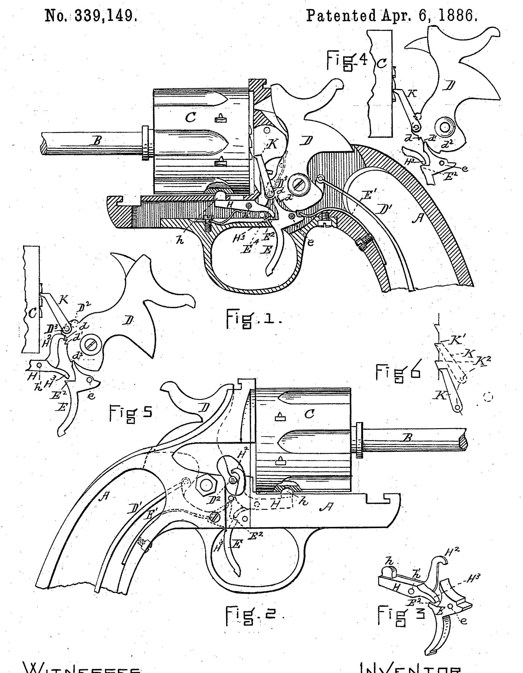
Figure 1 is a sectional view showing the operating parts in elevation. Fig. 2 is an elevation taken from the opposite side from that of Fig. 1, parts being broken out to show details. Fig. 3 is a perspective view showing the trigger and the stop-lever. Figs. 4 and 5 are elevations showing details, and Fig. 6 is a diagram to represent the action of the revolver-lever.
A in the drawings represents the stock; C, the revolver-chamber; B, the revolver-axle, and D the hammer. The hammer D is acted upon by the mainspring D’ in the usual manner, and has pivoted to its front lower part the revolver-lever K, as indicated at D^3, Fig. 1. The trigger E, Figs. 1 and 3, is pivoted at e, and is acted upon by the spring E’. This trigger, in addition to its pawl-point E^4, has a shoulder, E^2. This shoulder E^2 serves to act upon the point H^3 of the stop-lever H, the stop-lever H being pivoted at h’, and is provided with a stop-boss, h, (see Figs. 1, 2, and 3,) so that when the trigger is in a certain position— that is, when holding the hammer at half-cock— it, acting through the shoulder E^2 and the point H^3 of the stop-lever H, will release the revolver-cylinder. The stop-lever H has an upward-projecting arm, H^2, the upper end of which is so bent that it engages with the projection D^2 (see Fig. 2) on the rear side of the hammer, so that as the hammer is drawn back it, acting through the projection D^2 and the arm H^2, will draw the stop-lever H out of place and release the revolver-cylinder C. Thus I have two distinct mechanisms for operating the stop-lever. The lower part of the hammer is formed in a peculiar manner for a purpose which I will now explain.
In Fig. 1 the pawl-point E^4 is held by a resting-point on the hammer D, as shown near the safety-notch d. The safety-notch d is, as usual, quite near the resting-point, and the half-cock notch d’ is but a short distance from the safety-notch d, as shown in Figs. 1, 4, and 5; but it will be observed that the full-cock notch d^2 is comparatively remote from the other notches, so that the hammer has a long sweep in the moving from half-cock to full-cock— that is, this movement alone is sufficient, acting through the revolver-lever K, to make a full movement of the revolver chamber. By this arrangement I can have and maintain the revolver-chamber fastened or locked during the whole movement of the hammer from its firing-point to half-cock, so that there is no danger of the revolver-chamber getting out of place during the act of half-cocking. Another advantage of this construction is that the movement of the revolver-lever K through the full swing of the hammer from full-cock to the firing-point will be more than one notch of the revolver-ratchet. This is illustrated in the diagram, Fig. 6, in which the lever K, (indicated by dotted lines,) is in contact with the notch K’ when the hammer is at full-cock, and is considerably below the next notch K^2, as is indicated by the lever K, (in full lines,) when the hammer is at the firing-point. It is to be observed that the lever K always moves when the hammer moves, but it being so much below the notch K^2 the hammer may move from the firing-point to half-cock before the end of the lever K will engage with the notch K^2. Thus during the movement of the hammer from the firing-point to half-cock the revolver-chamber may remain locked, and precisely at this point. When the revolver-chamber is released, the revolver-lever K comes into contact with a notch, thus preventing the revolver-chamber from moving at all in the wrong direction.
I claim—
1. In a fire-arm, the combination of the revolver-chamber C, revolver-lever K, its ratchet and hammer D, said hammer having upon its lower limb a safety-notch, d, half-cock notch d’, and a full-cock notch, d, all so placed that the hammer may move from the firing-point to half-cock without causing any movement of the revolver-cylinder, and that the movement of the hammer from half-cock to full-cock will give the revolver-lever K sufficient motion to operate the revolver-chamber, with the trigger E, having a shoulder, E^2, and a stop-lever, H, all operating together, substantially as described, and for the purpose set fort.
2. In a fire-arm, the combination of the trigger E, having a shoulder, E, and the stop-lever H^2, having an arm, H, with the projection D^2 on the rear of the hammer D, all operating together substantially. as described, and for the purpose set forth.
GEORGE W. CILLEY.
Witnesses:
Hugh McInness,
William. H. Jennings, Jr.