
US 336894
UNITED STATES PATENT OFFICE.
GEORGE W. CILLEY, OF NORWICH, CONNECTICUT.
FIRE-ARM.
SPECIFICATION forming part of Letters Patent No. 336,894, dated March 2, 1886.
Application filed November 30, 1885. Serial No. 184,365. (No model.)
To all whom it may concern:
Be it known that I, George W. Cilley, of Norwich, in the county of New London and State of Connecticut, have invented certain new and useful Improvements in Fire-Arms, of which the following, taken in connection with the accompanying drawings, is a specification.
My invention relates more particularly to revolvers having double-action locks, the objects being to simplify the mechanical combinations by which the various actions of the parts of the lock are accomplished, especially relating to the sear and its lever, the stop-lever, and the mechanism for operating it, and the gate and its parts. These objects I obtain by the mechanism shown in the accompanying drawings, in which—
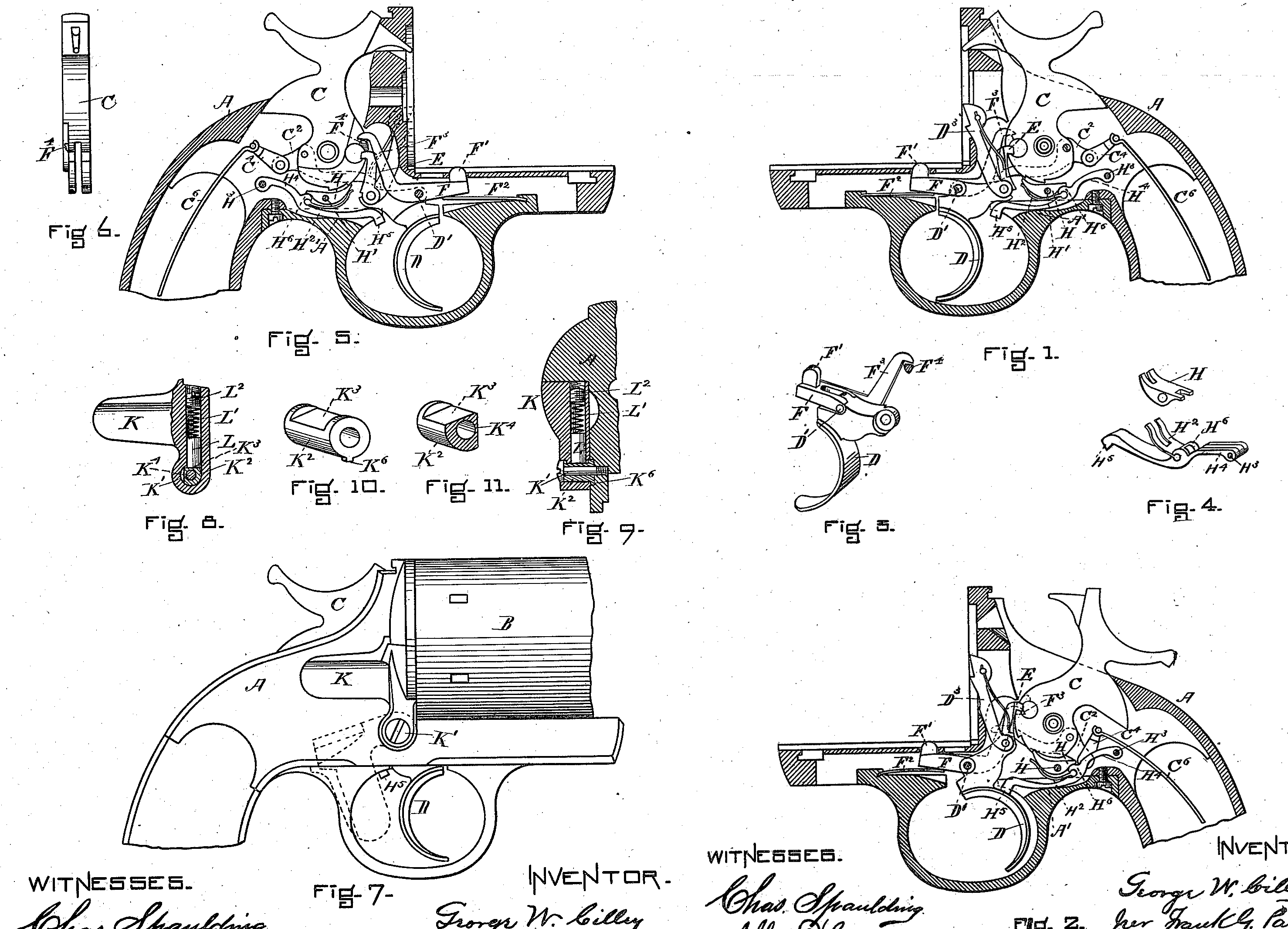
Figure 1 is a vertical longitudinal section of the stock, showing the lock in elevation, the hammer being down. Fig. 2 is a view of the Same, the hammer being up. Figs. 3 and 4 are details. Fig. 5 is a view similar to Fig. 1, taken from the opposite side. Fig. 6 is a front elevation of the hammer. Fig. 7 is a view showing the gate and a part of a revolver in elevation. Figs. 8, 9, 10, and 11 are details.
The stock A, hammer C, sickle-lever C^2, link C^4, spring C^6, revolver-lever D^3, and fly-pawl E are old and need no specific description.
H, Figs. 1, 2, and 5, represents a sear, which is pivoted at H’, and is acted upon tentatively by the spring H^2, for the purpose of throwing its forward end up so that it may engage with the notches in the hammer C, and positively by the boss H^6, which serves at the proper time to throw the rear end of the sear up and the forward end down, so as to disengage the front end from the notches of the hammer, and thus release the same and allow it to fire the cartridge. The spring H^2 and the boss H^6 are both directly connected to and move with the sear-lever H^4 H^5. Said sear-lever H^4 pivoted to the stock at H^3, and its front end, H^5, is so formed and placed that it will be acted upon by the trigger D, (see Fig. 2,)— that is, when at full-cock, as shown in Fig. 2, the backward motion of the trigger D will throw up the lever H^4 H^5, the boss of which H^6 coming in contact with the rear end of the sear H will throw the forward end of the same down and out of contact with the full-cock notch of the hammer C, and thus allow the hammer to act. As the sear-lever H^4 H^5 is limited in its downward motion by that part of the stock shown at A’, Figs. 1, 2, and 5, the spring H^2 is always pressing against the forward end of the sear, so that it (the sear) is always ready to engage with either of the notches of the hammer, the reaction of the spring being controlled by the stock at A’.
The sear H and the sear-lever H^4 H^5, together with the spring H^2, are shown in detail at Fig. 4, in which the sear H is represented as detached from the lever, so that the parts may be shown more clearly.
The stop mechanism of my device may be described as follows: F, Figs. 1, 2, and 5, is a stop-lever, the stop proper being shown at F’. This stop-lever has for its pivot D’ of the trigger D, and is held up by the spring F^2, Figs. 1, 2, and 5. Connected to the stop-lever F, I have a bent arm, F^3, (see Figs. 1, 2, 3, and 5,) the upright part of which is bent, as shown in Figs. 1, 3, and 5, so as to engage with the projection F^4 on the hammer C, Figs. 5 and 6. The upright part of the arm F^3 is flexible, and the lower side of the projection F^4 is beveled, so that as the hammer descends said projection will glide past, the hooked end of the arm F^3, but will engage positively with it when the projection moves upward, as it does in the beginning of the backward motion of the hammer. Thus the first action of the hammer is to lift up the arm F^3, and the same swinging upon the pivot D’ throws down the stop-lever F and disengages the stop F’ from the cylinder, so that the further backward motion of the hammer, acting through the fly-pawl E and the revolver-lever D^3, causes the cylinder to revolve in the usual manner.
I will now describe the gate and its parts, reference being had to Figs. 9, 10, and 11. The gate K, Figs. 7, 8, and 9, is pivoted on a post, K^2, Figs. 8 and 9, and is held to the stock by the screw K’, which passes through the center of the post K^2, as shown in Fig. 9. The inner end of this post K^2 is recessed into the stock, as shown in Fig. 9, and is provided with a lug, K^6, Figs. 9 and 10. This lug is to event the part K from turning upon its axis. This object can also be accomplished by making the inner end of the post square, so as to fit a corresponding recess in the stock. Within the upright part of the gate I place a spring-piston, L, a spring, L’, and a set-screw, L^2; all so arranged in connection with the post K^2, which has two flattened sides, K^3 K^4, that the gate K when closed will be held in that position, from the fact the spring-piston L rests firmly upon the flattened side K^3.
The gate K when opened, as shown by it dotted lines in Fig. 7, is held in place by piston L, resting firmly upon the flattened side K^4 of the post. The principal object of this construction is to prevent turning and loosening of the screw K, and also to present no loose or open joints into which dust or sand can enter.
I claim—
1. In a lock for fire-arms, the combination of the hammer C with the sear H, pivoted centrally, and the sear-lever H^4 H^5, said sear-lever having a boss, H^6, and an attached spring, H^2, and the trigger D, all substantially as described, and for the purpose set forth.
2. In a lock for fire-arms, the combination of the stop-lever F, pivoted on the trigger-pivot, and having a laterally-springing and flexible arm, F^3, with the hammer C, said hammer C having a wedge-shaped projection, F^4, all operating together substantially as escribed, and for the purpose set forth.
3. In a fire-arm, the combination of the gate K, having a spring-piston, L, with the stationary post K^2, said post having flattened e sides K^3 K^4, and being held in position by the screw K’, and the lug K^6, all operating together substantially as described, and for the purpose set forth.
In testimony whereof I have signed my name to this specification, in the presence of two subscribing witnesses, on this 23d day of November, A.D. 1885.
GEORGE W. CILLEY.
Witnesses:
Solomon Lucas,
Elisha P. Slocum.