
US 333725
UNITED STATES PATENT OFFICE.
JAMES BOLAND, OF NORWICH, CONNECTICUT, ASSIGNOR TO THE HOPKINS & ALLEN MANUFACTURING COMPANY, OF SAME PLACE.
REVOLVING FIRE-ARM.
SPECIFICATION forming part of Letters Patent No. 333,725, dated January 5, 1886.
Application filed November 18, 1885. Serial No. 183,159. (No model.)
To all whom it may concern:
Be it known that I, James Boland, a citizen of the United States, residing in the city of Norwich, county of New London, and State of Connecticut, have invented a certain new and useful Improvement in Revolving Fire-Arms, which improvement is fully set forth and described in the following specification, reference being had to the accompanying sheet of drawings.
My improvement is in that class of revolving arms commonly known as “double-acting,” the lock-work being so constructed that it may be used either as a “single-acting” or “self-cocking” arm.
In the sub-class to which my improvement is especially applicable the pawl or lever provided to rotate the many-chambered cylinder is pivoted to or in the rear side of the trigger, and my immediate object is to provide a more simple and at the same time less expensive spring device, to hold said pawl forward in constant engagement with said revolving cylinder, than has heretofore been in use. Among the various devices which have been used with more or less success is a flat sheet-steel spring secured to the rear lower side of the pawl, and whose free end extends well upward and engages one of the walls of the slot through which the pawl passes to reach the cylinder. This form of pawl-spring has been generally adopted by manufacturers of double-acting small-arms; but as far as I am acquainted with the state of the art is open to the following objections, which it is my purpose to overcome: First, when secured directly to the pawl there has been an inclination to work loose, caused by the constant jar in firing and working the arm; second, the considerable friction resulting from the rubbing of both the spring and pawl against the walls of the frame-slot at each downward movement of the pawl after firing acts directly against the force of the trigger-spring, and necessitates the use of a stronger trigger-spring than would otherwise be required. This is particularly objectionable in self-cocking arms, as it is desirable that the least possible force be exerted in pulling the trigger rearward.
In the device which I will proceed to describe in detail I have not only avoided the scribe in detail I have not only avoided the unnecessary friction above referred to, but have so formed and located the pawl-spring that it acts to assist the trigger-spring; and in order to more fully explain my device I have annexed hereto a sheet of drawings, in which—
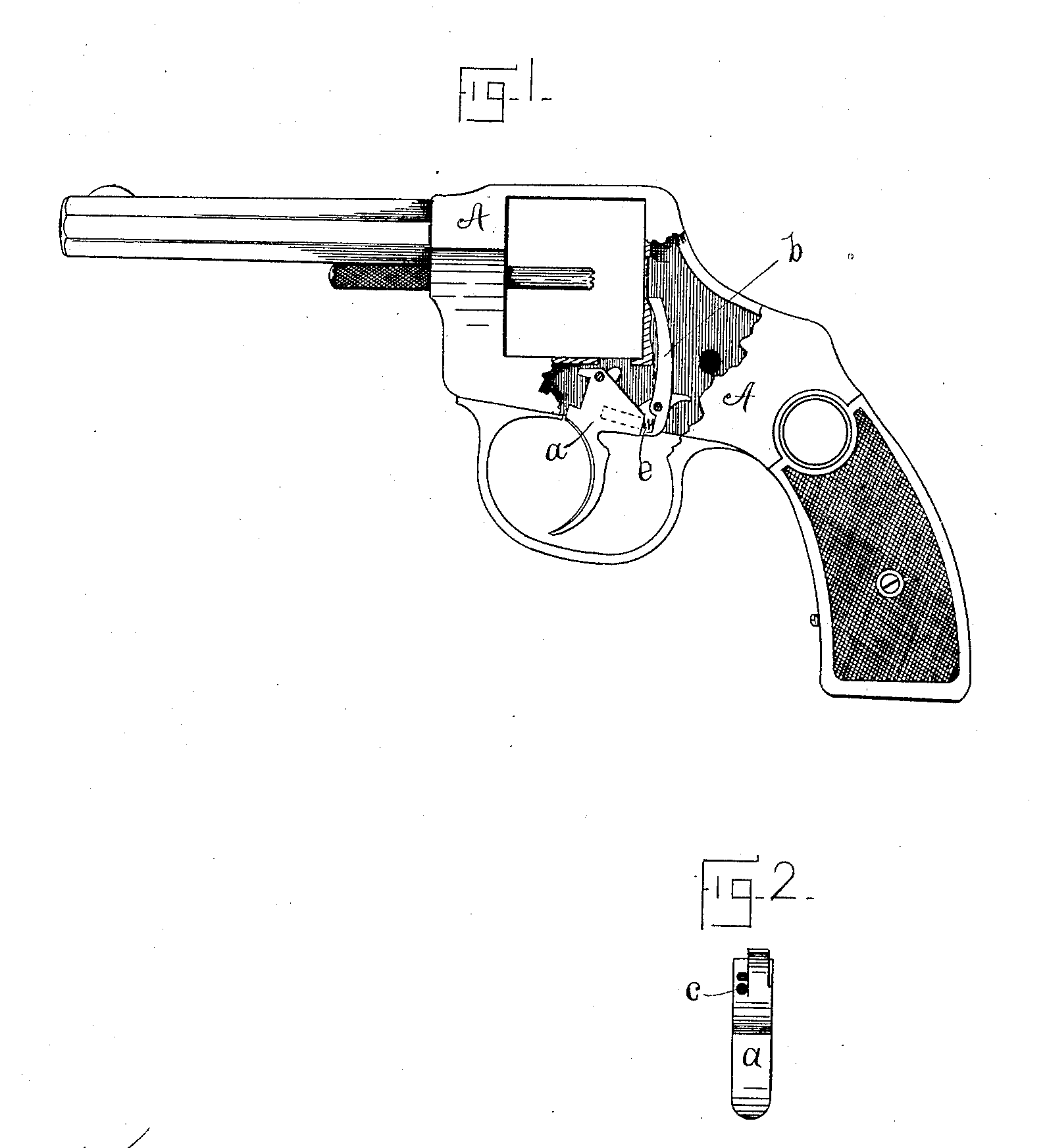
Figure 1 shows a portion of a revolver-frame, A, having properly located therein a trigger, a, and pawl b. Fig. 2 is a rear view of said trigger with pawl removed.
The pawl b is pivoted at the rear side of the trigger, said trigger being milled off or otherwise partially cut away so that the face of the pawl is flush with the side of the trigger when the parts are assembled. The upper portion of the pawl is of the customary shape; but the lower portion extends downward below the fulcrum, and is preferably slotted transversely, as shown. The side wall of the trigger, which confronts the short arm of pawl b, is drilled, as at c, Fig. 2, and in the hole thus provided I place a strong spiral spring, e, whose outer end engages the short hooked end of the pawl and acts constantly to throw the longer arm forward. The hole c should be bored at about a right angle to the engaging portion of the pawl, so that there may be little or no inclination on the part of the spring to cramp and bind when compressed.
With the parts assembled as described, and with the pawl proper resting forcibly against the frame, the tendency of spring e is to return the trigger to its normal position after firing; and I find in practice that it is both possible and practicable to dispense with the trigger-spring proper, (heretofore a necessary element in this class of arms,) and to depend altogether on said spring e, thus reducing the number of parts, and also reducing the cost of producing the complete arm.
Having thus described my invention, I claim—
1. In an arm of the class referred to, a trigger pivoted within a suitable frame, a cylinder-pawl pivoted to the rear of said trigger and having its lower portion extended below its pivotal connection, as herein described, and a spring held within a recess in the trigger, whose free end engages said lower portion of the pawl, said elements being combined, substantially as and for the purpose specified.
2. In combination with a suitable frame, a trigger, a pawl pivoted to the rear portion said trigger and having its lower portion extended below its pivotal point and slotted transversely, as described, and a spiral spring concealed within the trigger, capable of engaging the pawl, as described, for the purpose of throwing the longer arm of said pawl forward into engagement with the cylinder-ratchet.
JAMES BOIAND.
Witnesses:
Frank. H. Allen,
Tylerj, Howard.