
US 317965
UNITED STATES PATENT OFFICE.
JAMES BOLAND, OE NORWICH, CONNECTICUT.
REVOLVING FIRE-ARM.
SPECIFICATION forming part of Letters Patent No. 317,965, dated May 19, 1885.
Application filed February 27, 1885. (No model.)
To all whom it may concern:
Be it known that I, James Boland, a citizen of the United States, residing at Norwich, in the county of New London and State of Connecticut, have invented certain new and useful Improvements in Revolving Fire-Arms, which improvements are fully set forth and described in the following specification, reference being had to the drawings which form a part of and accompany said specification.
My invention relates, particularly, to a certain combination of mechanical devices by means of which all the empty cartridge-shells may be simultaneously ejected from a revolving arm after firing, my purpose being to attach such a device to so-called “solid-frame” revolvers— that is to say, to revolvers in which the barrel is Screwed into or formed as an integral part of the frame which contains the lock-work. By so doing I am able to provide a cartridge-ejecting mechanism which can be cheaply made, easily applied to solid-frame arms as now commonly constructed, and readily understood and operated by any one of average intelligence.
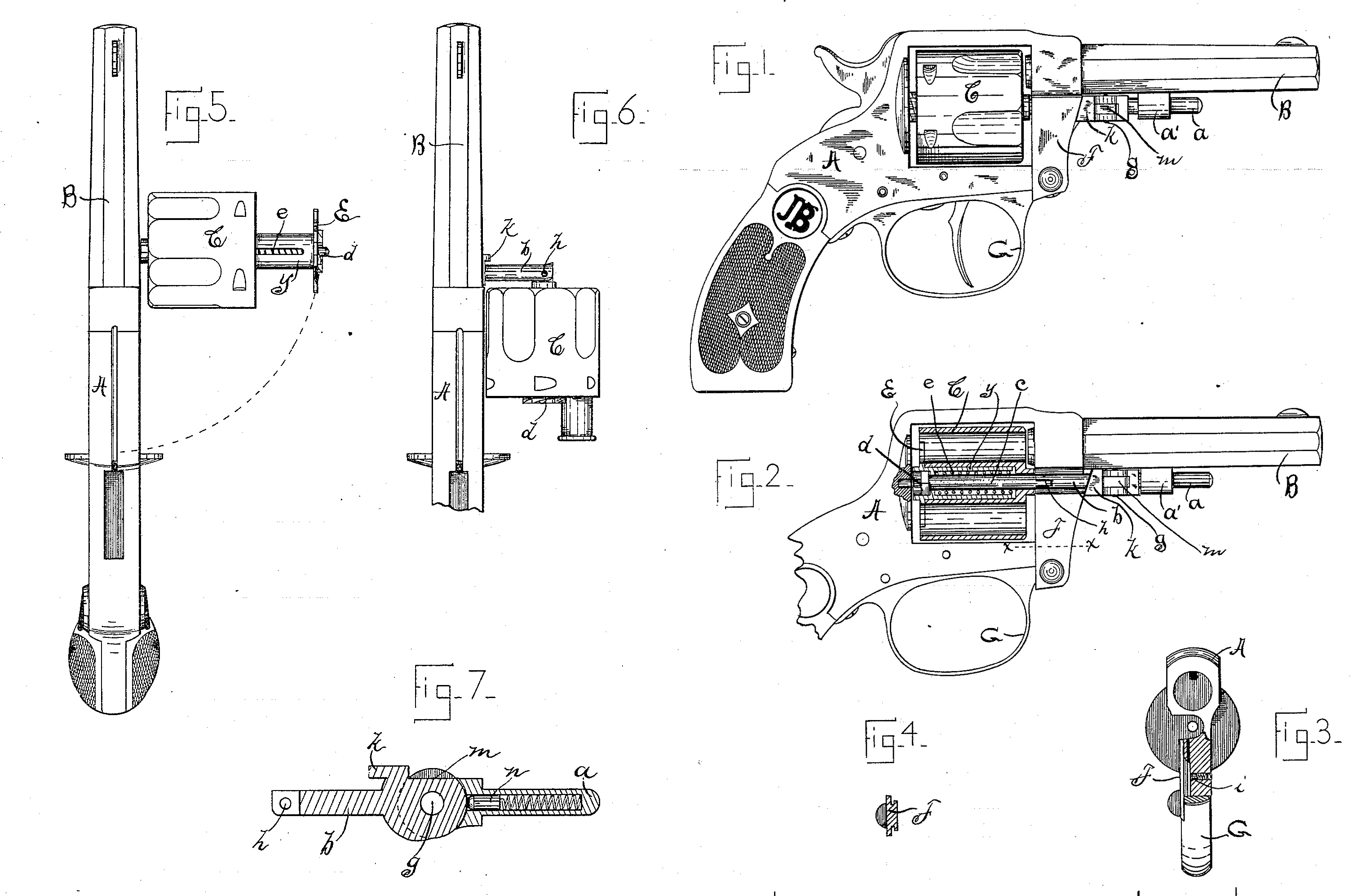
In order that my new device may be more fully understood and explained, I have annexed hereunto drawings of the same, Figure 1 being a side view of a complete revolver in which my improvements are embodied. Fig. 2 is a similar view of the revolver, (with stock cut away,) showing the cylinder and cartridge-ejecting mechanism in section. Fig. 3 is a front view of the frame, cut away to illustrate the means employed to lock slide F in said frame; and Fig. 4 is a cross-section of said slide on line x x of Fig. 2. Fig. 5 is a top view of said revolver, with the cylinder swung out to one side, as in the act of ejecting the cartridge-cases. Fig. 6 is a similar view, showing said cylinder returned to the proper position for reloading; and Fig. 7 is an enlarged view, in longitudinal section, of the jointed axial pin of the cylinder from the under side of said pin.
The letter A represents a revolver-frame; B, the barrel, screwed fixedly in said frame, and C the rotatable cylinder containing the several cartridges. The axial pin of said cylinder is composed, preferably, of four sections, a b c d, the forward section, a, being held and adapted to slide lengthwise in a lug, a’, which is attached to the under side of barrel B, or, if preferred, may be formed as an integral part of said barrel. Said complete axial pin has a longitudinal movement (with section a) sufficient to allow the reduced rear end of section d to enter a recess in the recoil-shield, for the purpose of providing a step or journal-bearing for said axial pin as the cylinder is rotated.
Cylinder C is counterbored from the rear end to receive the neck y of the ejector E, which ejector is substantially of the spider form patented by William C. Dodge, January 17, 1865, No. 45,912. Said ejector is formed with the neck or collar y, which enters the counterbored cylinder, and is drilled centrally to receive section c of the axial pin, said central hole being somewhat larger than the pin c to allow space for a spiral spring, e. Said central hole is provided near its rear end with an inwardly-projecting annular rib, against which one end of spring e abuts, the other end of said spring resting against the shoulder formed by counterboring cylinder C. Section d is screwed into the free end of pin c, and has a head which prevents the ejector from passing rearward, except as above provided, to enter its journal-bearing. It will be evident that sections c and d could, if desired, be formed integral, but for convenience in assembling I prefer the method herein shown. Sections b and c are hinged together at a point far enough forward to allow the cylinder to swing laterally to clear frame A, the longitudinal movement of the complete axial pin allowing the cylinder to move slightly rearward as it swings out of its place in the frame, to prevent said cylinder from cramping in said frame. Spring e, by its expansive power, acts with a constant tendency to force the ejector E and axial pin rearward, and to force the cylinder forward, or (when the cylinder is swung out of frame A) to slide the cylinder forward on the axial pin and away from the ejector, as shown in Fig. 5. Said spring also serves the additional purpose of holding the axial pin rearward in its step when the arm is in its normal position, as in Figs. 1 and 2. At a point at or near the front end of the cylinder the sections b and c are hinged together (see Figs. 2, 6, and 7, at h) for a purpose hereinafter explained.
F represents a slide, dovetailed or otherwise movably attached to the frame forward of the cylinder, and so constructed that it may be slid upward to cover both the axial pin above described and the frame recess in which said axial pin lies when in its normal closed position. This slide F is held open or closed by a spring-pressed friction-stud, i, or other similar suitable device, and is limited in its downward movement by the guard G, against which the dovetailed inner portion of slide F abuts when the desired movement is attained.
Secured to or formed integral with the axial pin is a lug or extension, k, which is cut diagonally on the side which confronts the cylinder to engage the correspondingly-formed front edge of slide F, so that when slide F is moved downward to expose and release the axial pin its inclined edge acts as a cam to force lug k and the axial pin forward, thus releasing section d from its step in the recoil-shield.
My device is operated substantially as follows: The slide F is slid downward until it abuts against the guard G. This action forces the axial pin forward, section a sliding in its bearing a’. The cylinder is now forced out of the frame, swinging on the joint g, and as soon as the forward end of the cylinder moves clear of the frame the spring e forces said cylinder toward joint g, the cartridges or shells being by the operation withdrawn and dropped. Prior to reloading the cylinder is drawn outward again over the ejector and the axial pin is broken at joint h, above referred to, until said pin and cylinder assume the positions shown in Fig. 6— that is to say, the cylinder is brought to a position parallel with the barrel and at a right angle to section b, which section thus bent acts to prevent springe from separating or forcing apart the ejector and cylinder.
To assist in retaining the several parts in the positions last described, I have flattened one edge of section b in its hinge portion, as at m, and have drilled section a centrally and placed therein a spring-pressed plug, n, which, as the cylinder is brought to the reloading position, rests on the flattened portion m with a tendency to hold said section b at a right angle to the barrel B. After loading, the cylinder is moved to straighten or line up the several sections of the axial pin, and is then swung into its place in frame A. The slide F is now moved upward to cover the axial pin by the same movement, releasing cam k and allowing the spring e to force the axial pin rearward into its step, when the arm is again ready for action.
Having thus described my invention, I claim—
1. In a revolving fire-arm, a cylinder, a laterally-swinging axial pin hinged forward of the frame and adapted to be slid longitudinally to release its rear end from its step in the frame, an ejecting device rotatably mounted on said axial pin within the cylinder and adapted to withdraw the cartridges as the cylinder is moved forward, and a spring or other similar suitable means for automatically forcing the axial pin rearward into its step when the cylinder is in its normal position in the frame, all being combined substantially as and for the purposes herein specified.
2. A revolver-frame, a barrel secured fixedly to said frame, a cylinder whose axial pin is hinged forward of the frame and adapted to be moved longitudinally, the cam-lug. k, formed as a rigid part of the axial pin, and the slide F, formed and located to engage and move said cam-lug as said slide is depressed, all being combined and used substantially as described, and for the object set forth.
3. An axial pin supported forward of the frame, capable of longitudinal movement in its support and provided with cam-lug k, and an engaging cam-slide located on the frame of the arm and by its movement acting on said axial pin to force it forward, all being combined substantially as and for the object specified.
4. In a suitable supporting-frame, a cylinder, a cartridge-ejector, a spring located within the cylinder and adapted both to force the cylinder forward away from the ejector and to force the axial pin rearward into its seat, and an axial pin hinged forward of the frame and capable of suitable longitudinal movement, all being combined substantially as and for the purpose specified.
5. In combination, a suitable supporting-frame, an axial pin hinged forward of said frame and provided near its central portion with the joint h, a cylinder, and an ejecting device located within said cylinder and rotatably located on said axial pin, all substantially as described, and for the purpose set forth.
6. In combination with the frame A and cylinder C, an axial pin for said cylinder, hinged forward of the frame, which slides longitudinally in its bearings to release its free end, and a spring so located on said pin that it acts with a constant tendency to throw said pin rearward, as and for the object specified.
7. In combination with frame A, barrel B, and cylinder C, a jointed sectional axial pin whose forward section is secured to barrel B, but is longitudinally movable in its support, and a spring-pressed plug concealed within said forward section, which, bearing against the flattened hinge portion of section b, acts to retain said section b at a right angle to the forward section while in the act of reloading, as and for the object specified.
8. In a revolving fire-arm, a cylinder, a jointed sectional axial pin hinged at its forward end, a frame recessed to receive said axial pin when in its closed position, a slide secured in said frame and capable of being moved vertically to expose or protect said axial pin, and a trigger-guard so located that it limits the movement of said slide, all being combined substantially as described.
JAMES BOLAND.
Witnesses:
Tyler. J. Howard,
Frank H. Allen.