
US 313048
UNITED STATES PATENT OFFICE.
WILLIAM. H. BLISS, OF NORWICH, CONNECTICUT
REVOLVING FIRE-ARM.
SPECIFICATION forming part of letters Patent No. 313,048, dated March 3, 1885.
Application filed February 14, 184. (No model)
To all whom it may concern:
Be it known that I, William. H. Bliss, of the city of Norwich, county of New London, and State of Connecticut, have invented certain new and useful Improvements in Revolving Fire-Arms, which improvements are fully set forth and described in the following specification, reference being had to the accompanying drawings, in which—
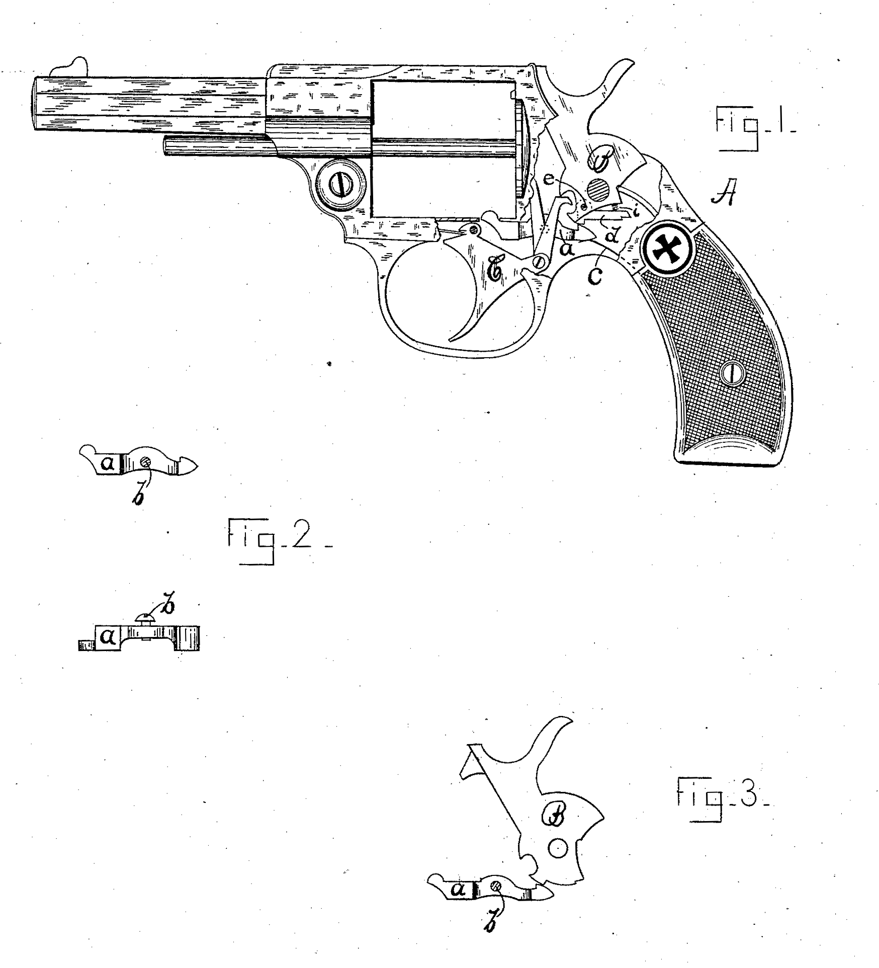
Figure 1 is a side view of a revolver containing my improvements, a portion of the frame being cut away to expose the working parts. In Fig.2 are shown side and top views of the cylinder – bolt detached. Fig. 3 is a detached view of said bolt and a hammer as commonly constructed.
My improvements relate, principally, to the bolt which stops and retains the cylinder of double-acting or self-cocking arms in position, so that the cartridge to be fired is in longitudinal alignment with the barrel proper, it being my purpose to provide a more simple and less expensive cylinder-bolt than is now commonly used.
My invention consists, briefly, of so constructing the forward part of the sear that it may act as a cylinder-bolt, thus dispensing with the cost and trouble of fitting an extra bolt, and reducing the number of working parts in the arm. In other words, I provide a single rocking or tilting piece with a hook on the rear end to engage the hammer-notches, and an upward extension on the forward end of the same piece, forming a nose to enter the cylinder-slots. To accomplish this I am obliged to make my combined sear and bolt of peculiar shape, as hereinafter described, so that the trigger and its connecting parts (hand, lifting-dog, &c.) may have room to act freely.
I have also changed and improved that portion of the hammer which engages the new form of Sear and bolt above referred to.
In the drawings herewith submitted, A represents the frame of an arm having hung in their respective places the hammer B and trigger C. Said trigger is of the usual form, and is pivoted in the frame just forward of the opening through which the nose of the bolt passes upward to engage the cylinder-notch, and has pivoted to its rear side a hand or pawl to revolve the cylinder, and a lifting-pawl, which, acting on the notched front side of the hammer, cocks said hammer when the trigger is forced or drawn rearward.
My combined bolt and sear is shown at a, it being pivoted to the back side of the frame by a short screw, b. (See Fig. 2, also dotted circle in Fig. 1.) This piece a, as before stated, has a rocking motion on said screw; but being acted on by a spring, as at c, the tendency is to throw the “bolt end” down and the “sear end” up into engagement with the hammer-notches.
When my new form of bolt is to be used with the common form of hammer— that is to say, with a hammer having notches formed as a solid part of said hammer, as in Fig. 3— I leave that part of the hammer against which the sear rests (when the hammer is down) somewhat fuller than usual, so that a considerable movement of the sear may be obtained as it drops off into the half-cock notch to throw the bolt-nose out of the cylinder, so that said cylinder may be rotated to load or to discharge empty shells. As the hammer continues to move upward the sear rides on its lower side until it drops into the full-cock notch, which, being of much less depth than the half-cock notch, allows the bolt-nose to enter the cylinder-slot far enough to keep the cylinder from turning. Now, as the trigger is pulled farther rearward its top side engages the under side of the bolt end, and, throwing it upward, releases the hammer, and at the same time forces the bolt up into the cylinder-notch. As the rear side of the trigger must pass upward by the sear, I cut away the central portion of said sear, as shown in the several figures.
In Fig. 1 I have hung in the lower side of the hammer what I call a “safety-latch,” d, on which the notches which are to engage the sear are formed. This safety-latch is pivoted in the hammer, as at e, its rear or free end being forced downward by a spring, i, said spring being of sufficient strength to overcome the spring c.
I have found in operating this new form of bolt an occasional tendency to jam against the periphery of the cylinder when said cylinder was not rotated far enough to allow the bolt to drop into the slot. In such a case the trigger could not be forced rearward far enough to throw out the sear and release the hammer; so I prefer to use a hammer containing a safety-latch, although by carefully fitting and adjusting the several parts a solid hammer may be used satisfactorily.
Having thus described my invention, I claim—
1. In combination with the hammer and trigger, a suitably-pivoted tilting piece having formed on its rear end a hook or sear to engage the hammer-notches, and on its forward end an upward extension to engage the cylinder-slots to retain the cylinder in a given position, said tilting piece being cut away near its central portion, and so located relative to the trigger that said trigger as it trips the sear shall also force the bolt end upward into the cylinder-slot, as and for the purpose specified.
2. In combination with the trigger and sear of a revolving arm, a hammer having pivoted in its lower portion, a spring-pressed fly or lever, as at d, having formed on its outer side half and full cock notches, and adapted to yield under proper pressure from the sear, all of said parts (trigger, sear, and hammer) being so formed and pivoted in the frame of the arm that they may operate substantially as and for the purpose specified.
WILLIAM. H. BLISS.
Witnesses:
Frank H. Allen,
A. H. Converse.