
British 242
Revolving Fire-arms.
LETTERS PATENT to James Kerr, of 17, Bedford Terrace, Trinity Square, Southwark, in the County of Surrey, Engineer, for the Invention of “ Improvements in the Construction of Revolving Fire-arms.’*
Scaled the 10th June 1859, and dated the 26th January 1859.
PROVISIONAL SPECIFICATION left by the said James Kerr at the Office of the Commissioners of Patents, with his Petition, on the 26th January 1859.
I, James Kerr, of 17, Bedford Terrace, Trinity Square, Southwark, in the County of Surrey, Engineer, do hereby declare the nature of the said Invention for “ Improvements in the Construction of Revolving Fire-arms,” to be as follows:—
This Invention relates, firstly, to a novel arrangement of those parts of repeating fire-arms employed for securing or attaching the barrel and frame to the stock.
And, secondly, to improvements in the means of imparting the rotatory motion to the chamber of repeating fire-arms.
Under the first head of my Invention I propose to forge the upper strap and barrel in one piece, and to hinge the lower portion of the frame to the barrel itself at the point near where the ramming plunger passes. The upper strap drops into a slot or recess made in the back portion of the frame, and the two are securely held together by a screw and by the passage therethrough of the cylinder rod.
Under the second head of my Invention I propose to impart the rotatory motion to the chamber by the rising and falling of the cock in the following manner:—The cylinder rod or spindle is made fast in the cylinder, and consequently revolves therewith. On the back end of this rod are cut right and left-hand spiral grooves, with an open or annular space between the commencement and termination of the right and left-hand spirals. A stud or projection on the cock (which is placed on one side of the lock plate, as described by me in my Provisional Specification of the 17th December 1858,) plays freely in these spiral grooves on raising or depressing the cock, and imparts the necessary intermittant rotatory motion to the cylinder. When the arm is at half-cock, the actuating stud or projection before referred to will occupy the intermediate or annular space between the two series of spiral grooves, and the cylinder will then be free to be rotated by hand for loading or other purposes. Suitable spring checks are applied in any convenient manner to prevent the chamber from turning tire reverse way.
By another arrangement a ratchet wheel may be fixed, or teeth may be formed on the base of the chamber or cylinder, and actuated by a rod or lever connected with the tumbler, a spring check acted upon by the tumbler being employed for keeping the chamber in a proper position for firing. Or, in place of fixing or forming the ratchet teeth on the base of the cylinder, the same may be applied to or formed on the back end of the cylinder rod outside the frame, and actuated as last described.
SPECIFICATION in pursuance of the conditions of the Letters Patent, filed by the said James Kerr in the Great Seal Patent Office on the 26th July 1859.
TO ALL TO WHOM THESE PRESENTS SHALL COME, I, James Kerr, of 17, Bedford Terrace, Trinity Square, Southwark, in the County of Surrey, Engineer, send greeting.
WHEREAS Her most Excellent Majesty Queen Victoria, by Her Letters Patent, bearing date the Twenty-sixth day of January, in the year of our Lord One thousand eight hundred and fifty-nine, in the twenty-second year of Her reign, did, for Herself, Her heirs and successors, give and grant unto . me, the said James Kerr, Her special license that I, the said James Kerr, my executors, administrators, and assigns, or such others as I, the said James Kerr, my executors, administrators, or assigns, should at any time agree with, and no others, from time to time and at all times thereafter during the term therein expressed, should and lawfully might make, use, exercise, and vend, within the United Kingdom of Great Britain and Ireland, the Channel Islands, and Isle of Man, an Invention for “ Improvehefts in the Constbuction op Revolving Fire-arms,” upon the condition (amongst others) that I, the said James Kerr, by an instrument in writing under my hand and seal, should particularly describe and ascertain the nature of the said Invention, and in what manner the same was to bo performed, and cause the same to be filed in the Great Seal Patent Office within six calendar months next and immediately after the date of the said Letters Patent.
NOW KNOW YE, that I, the said James Kerr, do hereby declare the nature of my said Invention, and in what manner the same is to be performed, to be particularly described and ascertained in and by the following, statement, reference being had to the accompanying Drawings, and to the letters and figures marked thereon, that is to say:—
My said Invention relates, firstly, to a novel arrangement of those parts of repeating fire-arms employed for securing or attaching the barrel and frame to the stock.
And, secondly, to improvements in the means of imparting the rotatory motion to the chamber of repeating fire-arms.
In practising the first part of my Invention, I forge the upper strap and barrel in o^e piece, having the lower portion of the frame and lower strap hinged to the barrel itself at the point near where the ramming plunger passes, whilst the upper strap forms a continuation of the barrel. The upper strap drops into a slot or recess made in the back portion of the frame, and the two are securely held together by a screw and by the passage therethrough of the cylinder rod.
In practising the second part of my Invention, I impart the rotatory motion to the chamber by the rising and falling of the cock in the following manner:— The cylinder rod or spindle is made fast in the cylinder, and consequently revolves therewith. On the back end of this rod are cut right and left-hand spiral grooves, with an open or annular space between the commencement and termination of the right and left-hand spirals. A stud or projection on the cock which is placed on one side of the lock plate, as described by me in the Specification of my Patent of December 17th, One thousand eight hundred and fifty-eight, plays freely in these spiral grooves on raising or depressing the cock, and imparts the necessary intermittant rotatory motion to the cylinder. When the arm is at half-cock, the actuating stud or projection before referred to will occupy the intermediate or annular space between the two series of spiral grooves, and the cylinder will then be free to be rotated by hand for loading or other purposes. Suitable spring checks are applied in any convenient manner to prevent the chamber from turning the reverse way.
By another arrangement a ratchet wheel may be fixed, or teeth may be formed on the base of the chamber or cylinder, and actuated by a rod or lever connected with the tumbler, a spring check acted upon by the tumbler being employed for keeping the chamber in a proper position for firing. Or, in place of fixing or forming the ratchet teeth on the base of the cylinder, the same may be applied to or formed on the back end of the short spindle, herein after referred to, or on the cylinder rod itself outside the frame, and actuated as last described.
Such being the nature of my said Invention, I shall now proceed more particularly to describe in what manner the same is performed, by reference to the several Figures on the Sheet of Drawings hereunto annexed, the same letters of reference indicating corresponding parts throughout all the Figures.
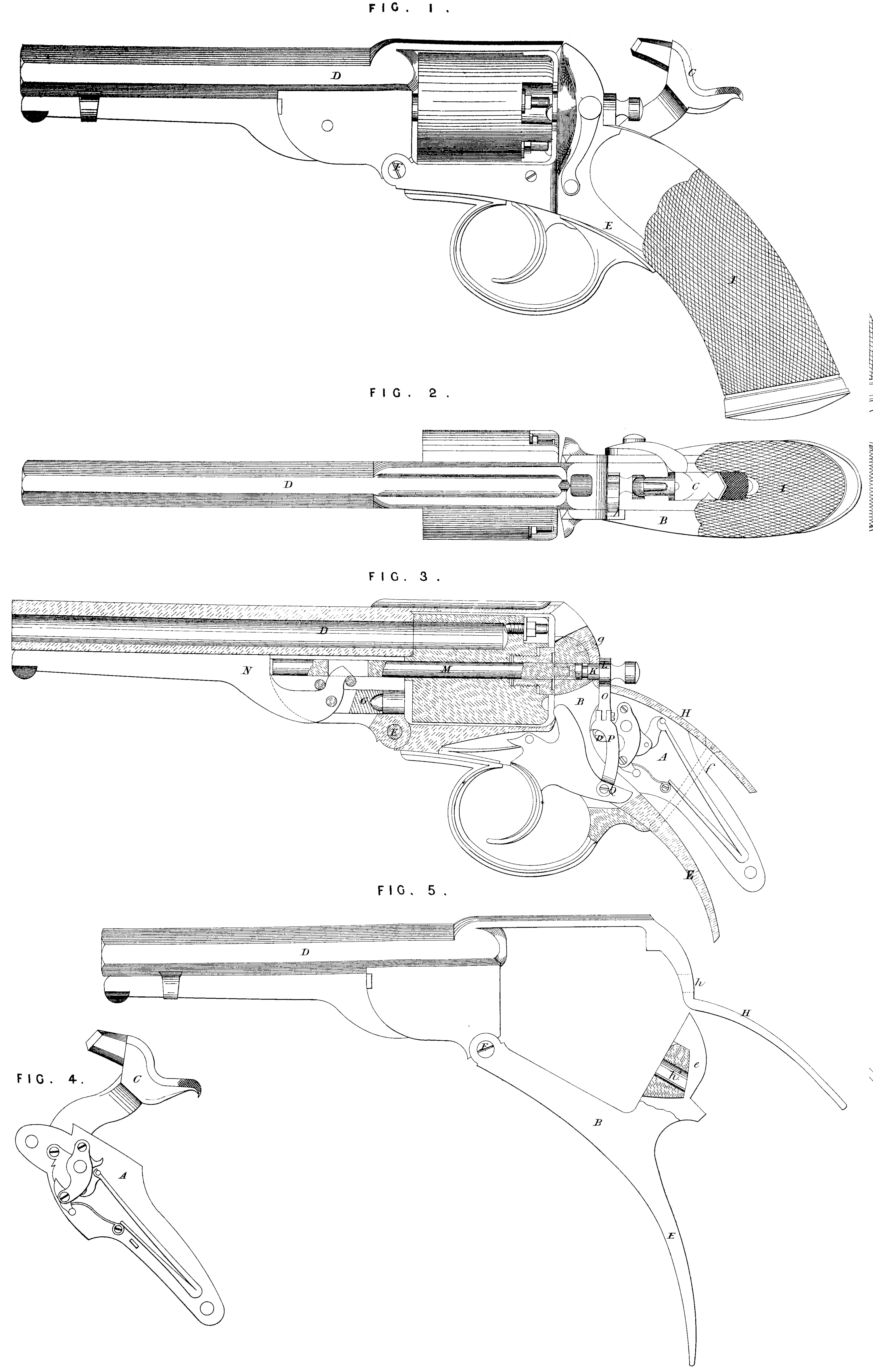
Figure 1 of my Drawings represents a full sized side elevation of a revolver pistol constructed according to my present Invention; Figure 2 is a corresponding plan of the same; Figure 3 is a longitudinal vertical section of the pistol with the barrel broken away; Figure 4 is an inside view of the lock detached, which is the ordinary gun or pistol lock; and Figure 5 represents a side elevation and partial section of the barrel frame and straps detached from the stock.
A is the ordinary and well-known gun or pistol lock shewn at Figure 4, which is detached from the body or frame B of the pistol, and is fitted with the usual cock C.
One important feature in my Invention is, that the barrel D of the pistol is forged separately or apart from the body or frame. By having the barrel forged separately from the frame greater facility is afforded for forging and making the parts, and for case-hardening the back part of the frame, whereby greater strength to resist the recoil of the cylinder is obtained, and less liability is incurred of the frame becoming damaged.
Another important advantage is, that the barrel can in case of injury be readily removed and replaced by a fresh one. The frame B and lowrer strap E is jointed at F to that part of the barrel through which the ramming plunger G passes into the chamber, whilst the hinder part of the barrel forms the upper strap H. This upper strap is let into the upper surface of the stock I, and drops into a recess e (Figure 5) formed in the body or frame, the two straps and stock being firmly secured together by a screw pin / (shewn in dotted lines at Figure S), passing through the upper strap and stock, and screwing into that portion of the body or framing forming the under strap, so that the stock is firmly gripped between the two straps. The upper strap and frame are still farther held together by another screw at g, and also by the cylinder rod which passes through the corresponding openings h, h\ (Figure 5,) made for that purpose in the frame and upper strap. K is a short spindle having a toothed or ratchet wheel L on one end, and the other passing through the body or frame of the pistol, and maintained in its proper position by a stud pin entering into an annular groove or channel cut in the short spindle, thereby allowing it to turn freely round, but keeping it fixed in its position longitudinally. The inner end of the short spindle which comes through tho body forms a socket to receive the end of the cylinder rod M, which is inserted from the front, and kept in its place by the lever ramrod N, as shewn in Figure 3. The cylinder rod and the bore at the base of the cylinder are so formed, that the cylinder cannot rotate without the rod, and the end of the rod and the socket of the short spindle are also made of such a shape as will prevent the one from turning without the other. It is thus obvious that on rotating the ratchet of the short spindle, the cylinder rod and cylinder will also be rotated ; this movement is derived from the rising and falling pall 0, which is jointed to the hooked link piece P, attached at Q to the trigger of the lock. The upper end of this pall passes up through a suitable aperture in the top strap, and is also toothed so as to form a rack, capable of fitting into the ratchet teeth of the small wheel on the end of the short spindle hereinbefore referred to. If found desirable, a protecting hood or cover may be placed over the ratchet wheel L and pall 0, for the purpose of protecting them from injury. This hood or cover may be fitted on to the end of the spindle, so that it may be withdrawn with the same. The act of raising the cock causes a stud p fitted in or formed on the side of the tumbler to operate upon tho hooked end of the link piece P, and thereby elevate it, thus raising the pall, and consequently turning the ratchet wheel and cylinder, whilst at the same time a stud formed on the trigger or on the link P is lifted into a recess in the base of the cylinder, thereby locking it for discharge. The pin which connects the end of the link piece P with the trigger blade is passed through a short slot formed in the link P, so that the trigger may just have sufficient play to release the tumbler before it commences to operate upon the mechanism for rotating the cylinder. By this simple contrivance, the cylinder may be kept always firm and steady without play or back lash. The cylinder rotating mechanism above described and illustrated on the Drawings may be slightly modified by dispensing with the short spindle K, and having the ratchet wheel formed on the hinder end of the cylinder rod, which would be inserted from the back and held in position longitudinally by a pin and ring groove, as before described. The rising and falling toothed pall which operates upon the ratchet wheel may be connected direct to the tumbler of the lock in place of to the trigger, by the intervention of the link piece P, as described in reference to the Drawings, whilst the locking of the cylinder into position for discharge may be effected by a spring stud ri>ing through the top strap, and entering & division of notches, also formed on the hinder part of the cylinder rod, the number of notches corresponding with the number of chambers in the cylinder. The tumbler of the lock by acting upon the spring stud at full and low cock locks the cylinder in position for discharge.
Having now described the nature of my said Invention, and the manner in which the same is carried into effect, I would observe that what I claim as the Invention secured to me by the herein*before in part recited Letters Patent is,—
First, the general construction, arrangement, and combination of parts of revolvers, as herein-before described.
Second, the forging of the barrels of revolvers apart from the body or frame when such body or frame is hinged or jointed to the barrel, in the manner and for the purpose herein-before described.
Third, the attaching the stocks of revolvers to the bodies or frames of such arms by means of an upper and a lower strap, combined in the manner hereinbefore described.
Fourth, the causing a portion of the hinder part or continuation of the barrel to drop into a recess made in the back part of the body or frame, and the securing of the two parts together, in the manner herein-before described.
Fifth, the peculiar constructions, arrangements, and combinations of mechanism for rotating the cylinders of revolvers, and locking the same for discharge, as herein-before described.
Sixth, the combination of the ordinary gun or pistol lock in “revolvers” with any one or more of the improvements included in the second, third, fourth, and fifth claiming clauses, as herein-before set forth.
In witness whereof, T, the said James Kerr, have hereunto set my hand and seal, this Fifteenth day of July, in the year of our Lord One thousand eight hundred and fifty-nine.
JAMES KERll. (l.s.)