
British 1634
LETTERS PATENT to Thomas Bailey, of New Orleans, United States, and of 17, Russell Street, Birmingham, in the County of Warwick, Gun Manufacturer, for the Invention of “ ImpbovejSehts in Repeating FIREARMS.”
Sealed the 5th October 1858, and dated the 20th July 1858.
PROVISIONAL SPECIFICATION left by the said Thomas Bailey at the Office of the Commissioners of Patents, with his Petition, on the 20th July 1858.
I, Thomas Bailey, of New Orleans, United States, and of 17, Russell Street, Birmingham, in the County of Warwick, Gun Manufacturer, do hereby declare the nature of the said Invention for “ Improvements in Repeating Fire-arms,'” to be as follows:—
My Invention consists in the first place in constructing the arm so that all the revolving movements are contained inside the body thereof. For this purpose I use a tumbler, the axle of which passes through the side of the body, and to which the cock is fixed in the ordinary manner and works on the outside of the body. The ratchet for working the revolving chamber is fixed on the pivot of the same, which pivot works through the body and is keyed to the chamber, the ratchet being worked by a lever connected to the tumbler. A washer of gutta percha, vulcanized india-rubber, or other similar material is placed on the pivot of the ratchet, so as to form an air-tight bearing where the pivot passes through the body to the back of the chamber.
My Invention consists in the second place in constructing the revolving chamber solid or without a hole through it for a spindle, but instead thereof, so as to revolve on two centres, one of which is fixed in the head of the body, so as to receive the back recoil, and the other in the breech or back part of the barrel, both of which are adjustable, in order to keep the revolving chamber in its true position. The nipples are inserted into the chamber parallel with its axis.
My Invention consists in the third place in connecting the barrel to the body of the arm by means of a hook joint, one part of which is on the under side of the body and the other on the breech or under side of the barrel, also on the top or upper side thereof by means of a stud or projection on the top strap passing into a suitably formed recess on the upper side or head of the body; and the barrel is fastened in its place by means of a revolving key with a spring connected therewith being made to hold the stud firmly in the said recess.
My Invention consists ih the fourth place in the following arrangement of the parts of the lock by which the hammer may be cocked either by hand or by the trigger. This is effected by means of a lever connected with the trigger acting on the tumbler, which when the discharge has taken place is made to slide down an incline on the tumbler by the action of a spring, thereby returning the trigger into its former position.
My Invention consists in the fifth place in cocking and discharging in the manner of an ordinary fowling-piece by means of the following arrangement of the parts :—The lever connected with the trigger above referred to is acted upon by the tumbler in such a manner as to cause the trigger to follow the tumbler up to “cock,” thereby allowing the arm to be discharged as an ordinary fowling-piece.
My Invention consists in the sixth place in stopping the revolving chamber by means of a spring stop acting on the ratchet at right angles thereto, and being moved into its required positions by a cam or projection on the tumbler.
My Invention consists in the seventh place in cutting a notch or cavity in the cap guard or cock nose, so that it may rest on the solid part of the chamber and retain the latter in a safe position.
And my Invention consists in the last place in forming a rack on the loader, and a toothed segment on^ the end of the lever, for the purpose of loading the chambers.
SPECIFICATION in pursuance of the conditions of the Letters Patent, filed by the said Thomas Bailey in the Great Seal Patent Office on the 20th January 1859.
TO ALL TO WHOM THESE PRESENTS SHALL COME, I, Thomas Bailey, of New Orleans, United States, and of Russell Street, Birmingham, in the County of Warwick, Gun Manufacturer, send greeting.
WHEREAS Her most Excellent Majesty Queen Victoria, by Her Letters Patent, bearing date the Twentieth day of July, in the year of our Lord One thousand eight hundred and fifty-eight, in the twenty-second year of Her reign, did, for Herself, Her heirs and successors, give and grant unto me, the said Thomas Bailey, Her special license that I, the said Thomas Bailey, my executors, administrators, and assigns, or such others as I, the said Thomas Bailey, my executors, administrators, and assigns, should at any time agree with, and no others, from time to time and at all times thereafter during the term therein expressed, should and lawfully might make, use, exercise, and vend, within the United Kingdom of Great Britain and Ireland, the Channel Islands, and Isle of Man, an Invention for “ Improvements in Repeating Fire-arms,'” upon the condition (amongst others) that I, the said Thomas Bailey, by an instrument in writing under my hand and seal, should particularly describe and ascertain the nature of the said Invention, and in what manner the same was to be performed, and cause the same to be filed in the Great Seal Patent Office within six calendar months next and immediately after the date of the said Letters Patent.
NOW ENOW YE, that I, the said Thomas Bailey, do hereby declare the. nature of my said Invention, and in what manner the same is to be performed, to be particularly described and ascertained in and by the following statement, reference being had to the Drawings hereunto annexed, and to the letters and figures marked thereon (that is to say):—
My Invention of “ Improvements in Repeating Fire-arms ’* consists in the first place in constructing the arm so that all the working and actuating movements are contained inside the body thereof. For this purpose I use a tumbler, the axis of which passes through the side of the body, and to which the cock is fixed in the ordinary manner and works on the outside of the body. The ratchet for working the revolving chamber is fixed on the pivot of the same, which pivot works through the body and is keyed to the chamber, tlie ratchet being worked by a lever connected to the tumbler. A washer of gutta percha, vulcanized india-rubber, or other similar material is placed on the pivot of the ratchet, so as to form an air-tight bearing where the pivot passes through the body to the back of the chamber.
My Invention consists in the second place in constructing the revolving chamber solid, or without a hole through it for a spindle, but instead thereof, so as to revolve on two centres, one of which is fixed in the head of the body, so as to receive the back recoil, and the other in the breech or back part of the barrel, both of which are adjustable in order to keep the revolving chamber in its true position. The nipples are inserted into the chamber, parallel with its axis or line of suspension.
My Invention consists in the third place in connecting the barrel to the body of the arm by means of a circular hook joint, one part of which is on the under side of the body, and the other on the breech or under side of the barrel; also on the top of the arm or upper side thereof by means of a circular stud or projection on the top strap of the barrel, passing into a suitably formed recess on the upper side or head of the body. And the barrel is fastened in its place by means of a partially revolving key with a spring connected therewith beiDg made to hold the stud firmly in the said recess.
My Invention consists in the fourth place in the following arrangement of the parts of the lock, by which the hammer may be cocked either by hand or by the trigger. This is effected by means of a lever connected with the trigger acting on the tumbler, which when the discharge has taken place is made to slide down an incline formed on the tumbler by the action of a spring, thereby returning the trigger into its former position.
My Invention consists in the fifth place in cocking and discharging in the manner of an ordinary fowling-piece by means of the following arrangement of the parts:—The lever connected with the trigger above referred to is acted upon by the tumbler in such a manner as to cause the trigger to follow the tumbler up to “cock,** thereby allowing the arm to be discharged as an ordinary fowling-piece.
My Invention consists in the sixth place in stopping the revolving chamber by means of a spring stop acting on the ratchet at right angles thereto, and being moved into its required positions by a cam or projection on the tumbler.
My Invention consists in the seventh place in cutting a notch or cavity in the cap guard or “ cock nose ” so that it may rest on the solid part of the., chamber and retain the latter in a safe position.
And my Invention consists in the last place in forming a toothed rack on the loader, and a toothed segment on, or small toothed wheel connected to the end of the lever for the purpose of loading the chambers.
Ilaving thus stated the nature of the said Invention, I will now proceed to describe more particularly in what manner the same is to be performed by reference to the accompanying Drawings, in which are represented the several parts of my repeating fire-arms above referred to.
Description of the Drawings.
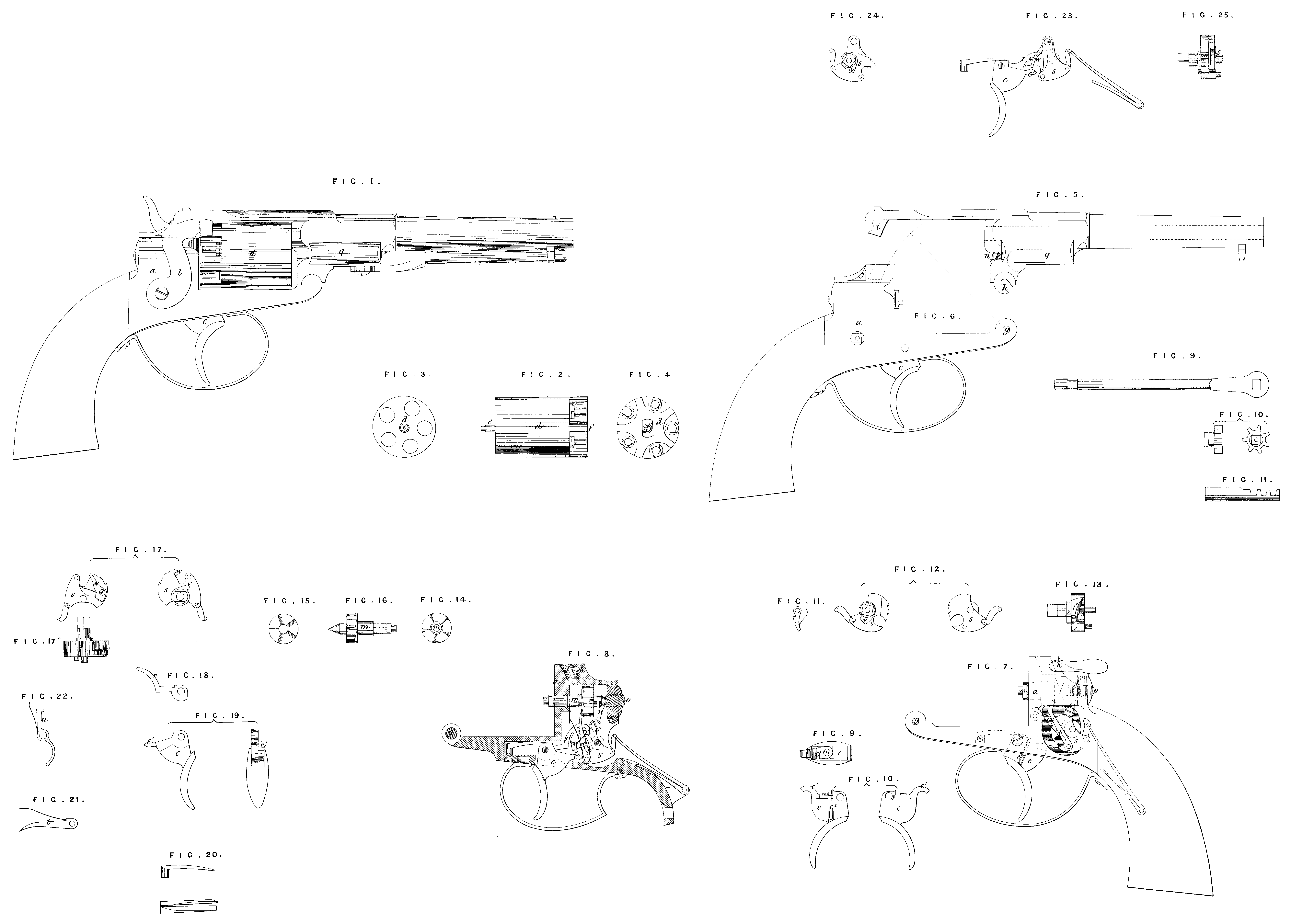
Fig. 1 is an elevation of a pistol constructed according to my Invention; and it is to be observed that in this and all the other Figures the same letters of reference indicate corresponding parts, a is the body of the pistol in which all the revolving movements are contained, so that the cock or hammer b and the tail or handle of the trigger c, and a small portion of the ratchet pivot at its junction with the revolving chamber, are the only parts of the lock which are visible on the outside thereof. Fig. 2 is a side elevation of the revolving chamber d9 detached ; Fig. 3 is a front, and Fig. 4 a back elevation of the same. This chamber is made solid, and is suspended on two centres, on which it revolves at e and /, one in front and the other at the back, which centres have their respective bearings in the body and the breech or back of the barrel, as herein-after described. It will be seen that the nipples are placed parallel with the axis or line of suspension of the chamber. It will also be seen on reference to Fig. 1 that the cock or hammer b rests on tho solid part of the back of the chamber, between two of the nippers when the cock is not in operation, a notch or cavity being formed on it.for the purpose of enabling it thereby to retain the chamber in the required position of safety. Fig. 5 represents the barrel and top strap, and Fig. 6 the body with the stock.
From these Figures will be understood the mode of connecting the barrel with the body of the fire-arm at the four points g9 k, i, j. This mode of connection will also be understood better on reference to Figs. 7 and 8, likewise Fig. 7 being a view of the body with the stock, similar to Fig. 5, except that the parts contained within the body are also shewn in Fig. 7, and Fig. 8 is a section of a body with a different action of the lock. Of the four points or means of connection between the barrel and the body g is a pin on the under side of the body, over which the hook h on the under side of the breech or back part of the barrel is fitted, then i is a stud or projection on the top strap l, which is inserted in the curved recess or cavity y, formed on the upper side or head of the body, the radius or centre from which the curve is struck being at g ; and h is a spring key which is turned so as to allow the curved stud or projection i to pass into the curved recess or cavity j9 and when . therein the key is again turned, so as to cause a portion thereof to enter the notch in the front of the stud or projection i, and thereby lock the parts together, the spring key retaining the said parts in firm connection. The key is shewn in section in Fig. 8 with the locking portion extending into the
recess or cavity j.
In Figures 7 and 8 is also shewn the back centre or pivot m of the revolving chamber d, the front centre or turning point being shewn at ny Fig. 5. Both these centres are adjustable, the former by means of the screw o (Fig. 8), and the latter by means of the screw p (Fig. 5). The pin e in the front of the chamber d is passed into the hollow space w, and the hollow space/ in the back of the chamber is fitted on to the stud on the end of the back centre or pivot m. And the chamber is adjustable in its bearings by turning the screw o, so as to press the outer end of the pivot m inwards, or in the direction of the chamber, also by turning the screw p, so as to shorten the length of the space in which the pin e is allowed to pass into its bearing at n, by bringing the end of the screw p forward therein and against the end of the pin e. It will thus be seen that the chamber having no longitudinal play, or what is sometimes called “ back lash,” receives the blow of the cock or hammer on its descent comparatively as solid and with as much force as any other arm. A washer of india-rubber, gutta percha, or other similar material is placed on the pivot m, (which is also the pivot of the ratchet for actuating the chamber,) so as to form an air-tight bearing where the pivot passes through the body to the back of the chamber. Fig. 9 represents the loading lever; Fig. 10, a small toothed wheel keyed to the end of the same, or a toothed segment may be formed on this end; and Fig. 11, the loader with a toothed rack formed on it. By turning the lever it will be obvious the loader will be forced into the loading chamber when required; q is the horizontal guide within which the loader is worked.
I proceed now to describe the several parts of the two locks represented at Figures 7 and 8, and the several detached Figures relating thereto respectively with the actions of the same.
Fig. 9 is a plan, and Fig. 10 the two side views of the trigger belonging to the lock above referred to under the fourth and fifth heads of my Invention, and represented at Fig. 7 : Fig. 11 shews the “ sear ” or “ dog * r for retaining the tumbler at cock ; Fig. 12 shews the two side views of the tumbler s, and Fig. 13 is an end view of the same, t (Fig. 7) is the pall or lever for turning the chamber by acting on the ratchet, and u is the spring stop lever for retaining the ratchet, and with it the chamber in its proper position, by passing into one of the notches at the back of the same, these parts being similar to those in the lock represented at Fig. 8. I have not thought it necessary to shew them detached, but they will be understood from the dotted lines in Fig. 7.
.The action of this lock is as follows:—When cocking by hand as in an ordinary fowling-piece, the lower part of the tumbler $ is made to press on the under side of the tail & of the trigger c, and thus to raise the trigger, the tail c1 being acted upon by a spring (so as to admit of its required lateral movement on its pivot) as the cock or hammer 6 rises into “half cock,** in which position it is retained by the “ sear *’ or “ dog ’* r, passing into one of the notches on the front part of the tumbler. At the same time the lower part of the spring stop lever u is acted upon by the cam v on the tumbler, so as to keep the upper part thereof out of the notch at the back of the ratchet of the revolving chamber d, thereby allowing the ratchet and chamber to be turned by hand for the purpose of loading, capping, &c. as required. On pulling the. lock into “ full cock,** the cam v of the tumbler is made to release the spring stop lever w, the upper part of which is immediately forced by its spring into the notch on the back of the ratchet, thereby holding the same with the chamber firmly in its place, the tumbler at the same time raising the trigger (through its connection with the tail c\ close under the “ sear *’ or “ dog” r. The trigger being now pulled back, the tail c1 forces the “ sear ” or “ dog ” r out of the notch in the tumbler s, and allows the cock or hammer to fall and discharge the arm. On the descent of the cock or hammer (at the discharge), the cam v on the tumbler presses against and passes the spring stop lever u9 leaving the upper part of the said lever in the notch of the ratchet, thereby holding the chamber in its proper position during the discharge of the arm. The trigger c is brought back again to its original position by the reaction of its spring, and with it the tail c1, which in returning slides down the incline t* on the tumbler, thereby collapsing its spring c2, and is brought into its original position under the tumbler by the reaction of the spring c2. In cocking by means of the trigger, the tail c] is caused to press against the tumbler in the recess into which it passes, and raise the tumbler with the cock or hammer, also to remove the “ sear ” or “ dog ’* r from the notch of the tumbler, and allow the cock or hammer to fall and discharge the arm, the parts returning to their original positions as before stated.
Fig. 14 is a front view of the ratchet for moving the chamber, shewing the ratchet teeth; Fig. 15 is a back view, shewing the notches therein for the upper end of the spring stop lever u to pass into and hold the chamber; and Fig. 16, an edge view of the same; Fig. 17 represents the two sides of the tumbler for the lock shewn at Fig. 8; and Fig. 17* is a plan view of the same; Fig. 18 is the “sear** or “dog;” Fig. 19, the trigger; and Fig. 20, the spring for the same, which it will be seen is divided so as to be capable of pressing both on the trigger and on the “sear” or “ dog** r connected thereto; Fig. 21 is the pall or lever for turning the ratchet and chamber, and Fig. 22 is the spring stop lever for retaining the same. These two with the ratchet are common to both locks.
The action of the lock shewn at Fig. 8 is as follows:—By drawing back the trigger c, the tail or projection cl will be brought into contact with the spring lever w, jointed to the tumbler s, which lever has an angle end forming a connection with the tumbler, so that the tail c1 of the trigger may, by pressing on the said lever, raise the tumbler, but is capable of passing the tumbler oil its return. The trigger is also formed so as on rising to bring a boss or solid part into contact with the “sear” or “dog” r, and withdraw the latter from the notch of the tumbler, so as to liberate the cock or hammer. And in cocking by hand, the trigger with its tail or projection c1 will be drawn back or raised by the lower part of the tumbler being moved under it, so as to bring the parts into the same relative positions as when acted upon through the trigger. The movement of the chamber d is effected in a similar manner to that described above, with reference to the lock shewn at Fig. 7.
Fig. 23 represents another modification of the lock adapted for firing by cocking either by hand or through the trigger on the same general principle as above described, but in this case that part of the tumbler s on which is placed the notches for “half cock ” and “full cock ” is convex in the direction of an arc struck from the radius towards the centre of the same. The tumbler is shewn detached at Figures 24 and 25, also the “ sear ” or “ dog ” r is in one solid piece with the trigger, and will fall into the notches for “ half cock ” and “ full cock ” respectively, when the tumbler is raised by lifting the hammer, or the lock can be fired by drawing back the trigger, so as to raise the tumbler by the pressure of the tail c1 on the bottom of the spring lever w. It will be seen on reference to the Drawing, that the notches on the tumbler are arranged so as to suit the altered position of the “ sear ” or “ dog ” r, and that in cocking by hand the trigger c will be drawn back or raised by the convex part of the tumbler s moving under the sear or dog r, so as to bring the parts into the same relative positions as when acted upon through the trigger as before described.
Having thus described the nature of the said Invention, and in what manner the same is to be performed, I would have it understood that my Invention may be varied in some of the details represented and described without departing from the principle or essential features herein stated; but I claim as of my Invention,—
First, the construction of the fire-arm so as to inclose all the working or actuating movements within the body.
Secondly, the construction of the revolving chamber solid, so as to work on two adjustable centres of suspension, instead of in the ordinary way, or on an axis passed through it; also the application of a washer to form an air-tight bearing for the back pivot.
Thirdly, the mode described of connecting the barrel to the body.
Fourthly, the general arrangement and construction of the locks represented at Figures 7, 8, and 23 respectively, as capable of being cocked through the trigger.
Fifthly, the same as being capable of being cocked by hand, as in an ordinary fowling-piece.
Sixthly, the stopping or retaining of the revolving chamber by means of a spring stop acting on the ratchet, such stop being actuated by a cam on the tumbler.
Seventhly, the forming of a notch or cavity in the “ cap guard ” or “ cock nose,” so that it may rest on the solid part of the chamber, and retain it in a safe position.
And, lastly, the forming of a toothed rack on the loader, so that it may be worked by a toothed segment on the end of the lever, or a small toothed wheel connected to the lever for the purpose of loading the chambers.
In witness whereof, I, the said Thomas Bailey, have hereunto set my hand and seal, the Seventeenth day of January, in the year of our Lord One thousand eight hundred and fifty-nine.
THOMAS BAILEY, (l.s.)
Witness,
John F. Swinburn,
Birmingham,
Gun Maker.