
British 1623
LETTERS PATENT to Charles Reeves, of Birmingham, in the County of •Warwick, Manufacturer, for the Invention of “Improvements in Repeating Fire-arms,”
Sealed the 5th October 1858, and dated the 19th July 1858.
PROVISIONAL SPECIFICATION left by the said Charles Reeves at the Office of the Commissioners of Patents, with his Petition, on the 19th July 1858.
I, Charles Reeves, of Birmingham, in the County of Warwick, Manufacturer, do hereby declare the nature of the said Invention for “ Improvements in Repeating Fire-arms,” to be as follows:—
My Invention consists, firstly, in the following method of constructing the locks of repeating fire-arms. I effect the raising of the hammer by means of a tooth fixed on the lower part of the said hammer engaging with a tooth on the trigger, the latter tooth urging forward the former when the trigger is depressed, and thereby raising the hammer. After the hammer has been raised to the required height, the tooth on the trigger escapes from the other tooth, and the hammer falls. One of the teeth must turn upon a joint so as to pass the other on the return motion of the trigger. The depression of the trigger on the raising of the hammer by hand, and the holding of the hammer at half cock and full cock, may be effected by the mechanism described and represented in the Specification of a Patent granted to me, bearing date the Twenty-fourth day of December, One thousand eight hundred and fifty-seven.
My Invention consists, secondly, in the following methods of constructing the axis on which the revolving chamber of repeating fire-arms works. According to one method I make the said axis a quick threaded screw. The said screw engages in a screw box formed in the anterior part of the frame in which the revolving chamber works. The said screw permits of the ready and rapid removal of the revolving chamber for cleaning and other purposes. According to the other method of constructing the axis of the revolving chamber, I make the axis in two parts, one part being carried by the revolving barrel, the other part working in the anterior part of the frame carrying the barrel. That part of the axis carried by the barrel is drawn into the said barrel by a spring, but is forced out by the part of the axis which screws into the frame. The said screwing part of the axis, by entering the anterior part of the barrel, forms a centre on which that end turns, and forcing out the portion of the axis in the interior of the barrel, forms a centre on which the other end of the barrel turns.
SPECIFICATION in pursuance of the conditions of the Letters Patent, filed by the said Charles Reeves in the Great Seal Patent Office on the 17th January 1859.
TO ALL TO WHOM THESE PRESENTS SHALL COME, I, Charles Reeves, of Birmingham, in the County of Warwick, Manufacturer, send greeting.
WHEREAS Her most Excellent Majesty Queen Victoria, by Her Letters Patent, bearing date the Nineteenth day of July, in the year of our Lord One thousand eight hundred and fifty-eight, in the twenty-second year of Her reign, did, for Herself, Her heirs and successors, give and grant unto me, the said Charles Reeves, Her special licence that I, the said Charles Reeves, my executors, administrators, and assigns, or such others as I, the said Charles Reeves, my executors, administrators, and assigns, should at any time agree with, and no others, from time to time and at all times thereafter during the term therein expressed, should and lawfully might make, use, exercise, and vend, within the United Kingdom of Great Britain and Ireland, the Channel Islands, and Isle of Man, an Invention for “ Improve–jxents in Repeating Fire-arms,” upon the condition (amongst others) that I, the said Charles Reeves, my executors or administrators, by an instrument in writing under my, or their, or one of their hands and seals, should particularly describe and ascertain the nature of the said Invention, and in what manner the same was to be performed, and cause the same to be filed in the Great Seal Patent Office within six calendar months next and immediately after the date of the said Letters Patent.
NOW KNOW YE, that I, the said Charles Reeves, do hereby declare the nature of the said Invention, and in what manner the same is to be performed, to be particularly described and ascertained in and by the following statement thereof, that is to say:—
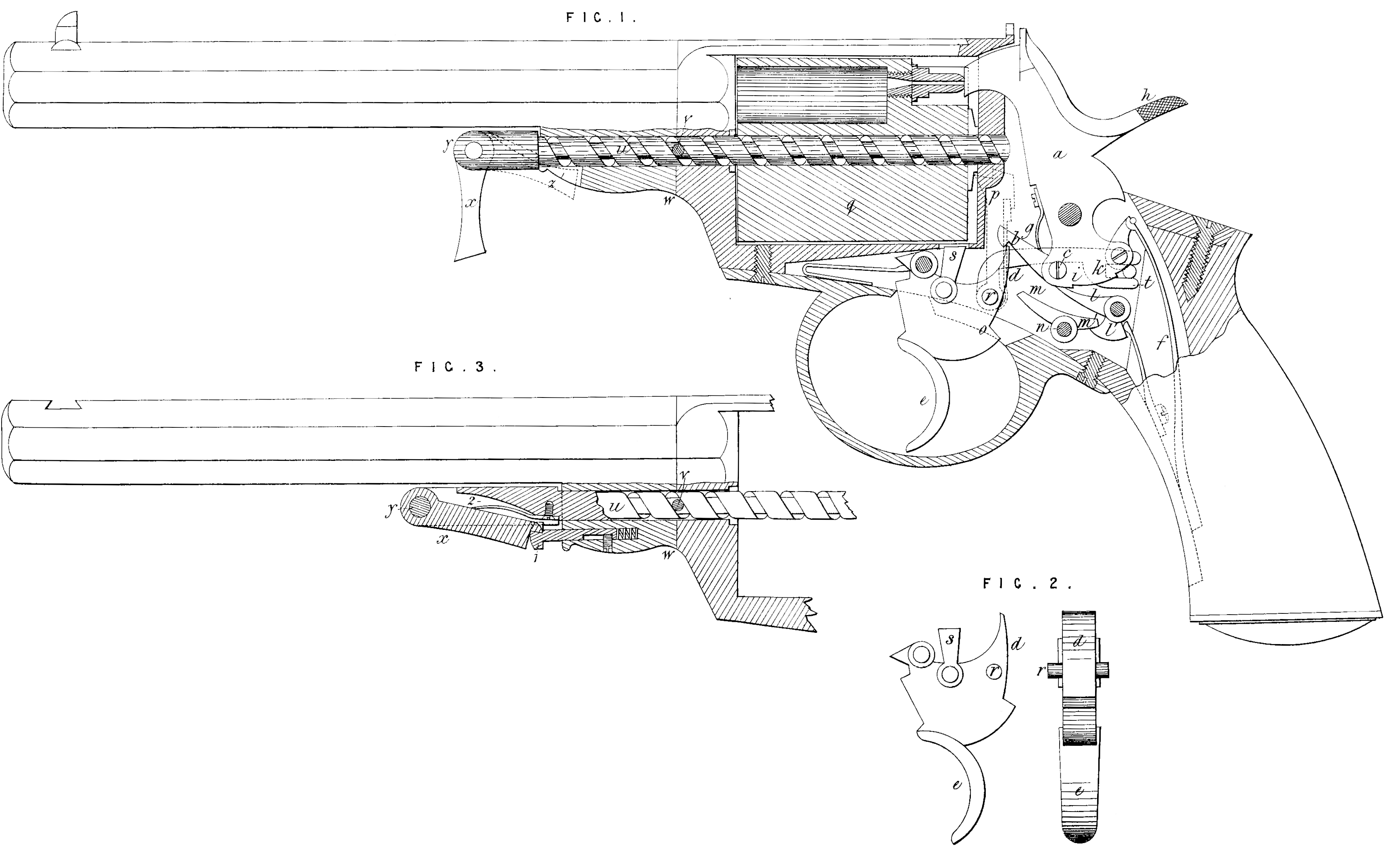
My Invention consists, firstly, in the method herein-after described, and illustrated in the accompanying Drawing, of constructing the locks of repeating fire-arms.
Figure 1 represents in vertical longitudinal section a repeating pistol constructed according to my Invention. The hammer a is raised by means of a tooth or lever 5 jointed at c to the lower part of the hammer a. A tooth d on the upper part of the trigger e engages with the hooked end of the tooth or lever b. By pressing the trigger e, the tooth d lifts the tooth or lever b, and raises the cock or hammer a. When the trigger e has been pressed nearly to the full extent of its motion, the tooth d escapes from the tooth or lever b, and the hammer falls by the action of the main spring/, and discharges the pistol. The tooth or lever b is kept to its bearing by a spring g.
When the hammer or cock a is raised by pressing upon the comb h of the cock instead of upon the trigger e, the said hammer is held in half cock and full cock by the bents i, 1c, respectively with which said bents the sear l engages. The said sear l is disengaged from the bent Jc on the discharge of the pistol in the following manner:—m, m\ is a lever turning upon a centre n, the end ml of the said lever engages with the tail Z1 of the sear l in the manner represented in the Drawing. When the trigger e is pressed, the part o of the trigger coming in contact with the end m of the lever m, m1, disengages the sear l from the bent h, and the hammer a falls, p is the driver by which the revolving chamber q is carried round, the said driver p is jointed to the trigger at r. The bolt by which the revolving chamber q is locked during discharge is also jointed to the trigger and marked s; Figure 2 represents the trigger e in side and back elevation. The depression of the trigger e when the hammer a is raised by pressing the comb h of the cock, is effected by the forked lever t and parts connected therewith, but as the said mechanism. for the depression of the trigger, when the cock is raised by hand, constitutes no part of my present Invention, and is described and represented in the Specification of a Patent granted to me bearing date the Twenty-fourth day of December, in the year of our Lord One thousand eight hundred and fifty-seven, I do not think it necessary herein to describe the same. : My Invention consists, secondly, in the method herein-after described, and represented in Figures 1 and 3 of the accompanying Drawing, of constructing and fixing the axis on which the revolving chamber of a repeating fire-arm works. Figure 3 represents in elevation a portion of a repeating fire-arm, the axis of the revolving chamber of which is constructed and fixed according to my Invention, and the same kind of axis is represented in Figure 1. In both Figures 1 and 3, I have omitted the loading rod usually attached to repeating fire-arms, as, by the omission of the said loading rod in the Drawing, the construction and method of fixing the axis of the revolving chamber is made more evident. The axis u consists of a quick-threaded screw, which engages with a pin v screwed into the side of the anterior part of the frame w, in which the revolving chamber works. The end of the pin v taking into the thread of the screw u, the said screw on being made to rotate is caused to advance or recede in the frame w and the revolving chamber q. On the outer end of the screw u a lever x is jointed, which said lever turning freely about the joint y may be used for turning and withdrawing the screw u. By the use of the quick-threaded screw u the revolving chamber q may be readily removed for cleaning and other purposes. The lever x when not in use may be turned down, so as to make its free end enter a slot at z, Figure 1, or may engage behind a spring stud fastening 1, in Figure 3. A spring 2 may be placed at the back of the lever x, so as to throw it out, when, by pressure upon the stud 1, it is liberated from the said stud.
Having now described the nature of my said Invention, and the manner of carrying the same into effect, I wish it to be understood that I do not limit myself to the precise details herein described, as the same may be varied without departing from the nature of my Invention; but I claim as my Invention,—
Firstly, the improvements in the locks of repeating fire-arms, herein-before described, and represented in the accompanying Drawing, that is to say, the mechanism for raising the hammer or cock, and liberating the said raised hammer or cock by pressure upon the trigger, and the mechanism for holding the hammer or cock at half and full cock, and of liberating the cocked hammer when the said hammer has been cocked’by pressure upon the comb of the said hammer.
Secondly, the method herein described, and illustrated in the accompanying Drawing, of constructing and fixing the axis on which the revolving barrel of a repeating fire-arm rotates, that is to say, making the said axis a quick-threaded screw, engaging in the anterior part of the frame in which the revolving chamber works, so as to advance or recede in the said frame when the said axis is made to rotate.
In witness whereof, I, the said Charles Reeves, have hereunto set my hand and seal, this Fifteenth day of January, in the year of our Lord One thousand eight hundred and fifty-nine.
CHARLES REEVES. (l.s.)
Witness,
H. P. Goodwin.