
British 1593
Repeating Fire-arms.
LETTERS PATENT to Richard Brazier, of Wolverhampton, in the County of Stafford, Manufacturer, for the Invention of “ Improvements nr Repeating Fire-arms.”
Sealed the 25th September 1858, and dated the 15th July 1858.
PROVISIONAL SPECIFICATION left by the said Richard Brazier at the Office of the Commissioners of Patents, with his_ Petition, on the 15 th July 1858.
I, Richard Brazier, of Wolverhampton, in the County of Stafford, Manufacturer, do hereby declare the nature of the Invention for “ Improvements rn Repeating Fire-arms,” to be as follows:—
My Invention consists, firstly, in the following methods of constructing the locks of repeating fire-arms. The raising of the cock by the trigger is effected by a hooked link or lever on the tumbler of the cock taking into the top of the trigger, the shape of the hooked link being such that it is disengaged when the trigger is pressed to the full extent of its motion. The mainspring of the lock is jointed to the said hooked link or lever. The hammer is held in cock by a sear on the upper part of the lock engaging in bents on the front of the cock, which sear is disengaged by the trigger on the discharge of the fire-arm. The driver by which the revolving barrel is turned is jointed to a plate turning upon the same centre as the hammer, and the said plate is urged forward when the cock is raised by a projection on the side of the tumbler. In the said plate is a slot in which a pin on the side of the upper part of the trigger engages. When the hammer is raised by the thumb, the said plate draws back the trigger by means of the slot and pin described. The revolving barrel is fixed by means of a lever raised by the trigger. I sometimes make the bents by which the hammer is held in cock on the side of the hammer, and place a sear to engage with the said bents on the side of the lock case, the said sear working in a plane at right angles to that in which the cock works.
My Invention consists, secondly, in the following method of constructing tbe loading rods of repeating fire-arms. A lever is jointed to the under side of the fixed barrel; the short end of the said lever is bent near the joint nearly at right angles to the long arm of the said lever. The said short end has a curved form nearly resembling a quadrant, and engages in the divided top of the loading rod under an antifriction roller on the top of the said rod. When not in use, the lever lies against the under side of the fixed barrel. By turning the said lever upon its joint, the loading rod may be made to enter and retire from the barrels in the revolving chamber, and by entering the said barrels to force the charge therein.
SPECIFICATION in pursuance of the conditions of the Letters Patent, filed by the said Richard Brazier in the Great Seal Patent Office on the 12th January 1859.
TO ALL TO WHOM THESE PRESENTS SHALL COME, I, Richard Brazier, of Wolverhampton, in the County of Stafford, Manufacturer, send greeting.
WHEREAS Her most Excellent Majesty Queen Victoria, by Her Letters Patent, bearing date the Fifteenth day of July, in the year of our Lord One thousand eight hundred and fifty-eight, in the twenty-second year of Her reign, did, for Herself, Her heirs and successors, give and grant unto me, the said Richard Brazier, Her special licence that I, the said Richard Brazier, my executors, administrators, and assigns, or such others as I, the said Richard Brazier, my executors, administrators, and assigns, should at any time agree with, and no others, from time to time and at all times thereafter during the term therein expressed, should and lawfully might make, use, exercise, and vend, within the United Kingdom of Great Britain and Ireland, the Channel Islands, and Isle of Man, an Invention for “ Improvements in Repeating Fire-aims,’* upon the condition (amongst others) that I, the said Richard Brazier, my executors or administrators, by [an instrument in writing under my, or their, or one of their hands and seals, should particularly describe and ascertain the nature of the said Invention, and in what manner the same was to be performed, and cause the same to be filed in the Great Seal Patent Office within six calendar months next and immediately after the date of the said Letters Patent.
NOW KNOW YE, that I, the said Richard Brazier, do hereby declare the nature of the said Invention, and in what manner the same is to be performed, to be particularly described and ascertained in and by the following statement thereof, that is to say:—
My Invention consists, firstly, in the method herein-after particularly described, and illustrated in the accompanying Drawing, of constructing the locks of repeating fire-arms.
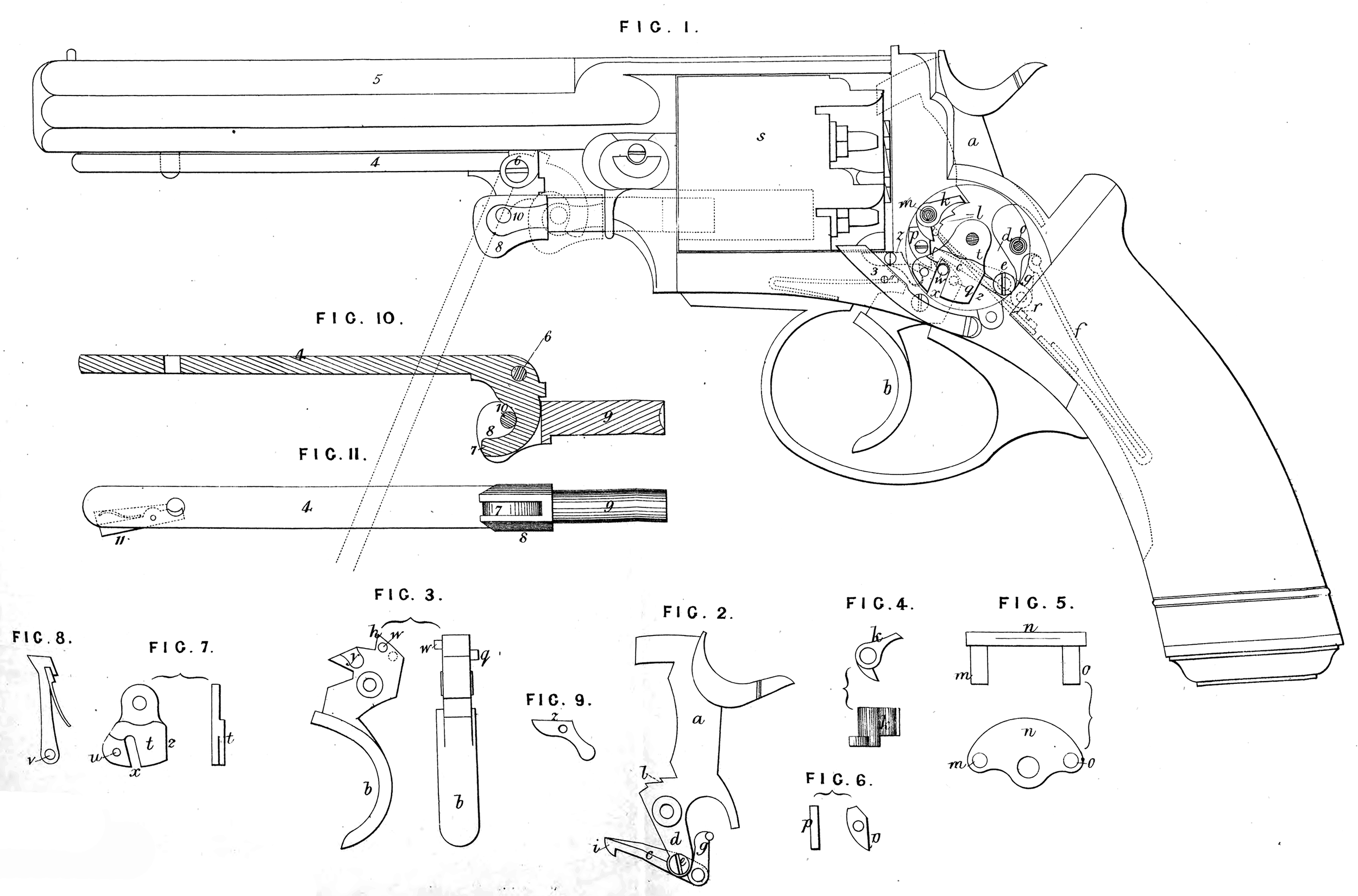
Figure 1 represents in elevation a repeating pistol, constructed according to my Invention; and Figures 3,4, 5, 6, 7, 8, and 9, represent detached portions of the same, as herein-after explained. The same letters indicate the same parts in the several Figures. The raising of the cock a by the trigger b is effected in the following manner:—A hooked link or lever c, shown in connection with the hammer a in Figure 2, is jointed to the tumbler d of the cock at e. The mainspring / of the lock is connected with the lever c by means of the connecting link g. The top h of the trigger b, shown separately in Figure 3, engages with the hooked end i of the lever c (see Figure 2), the shape of the hooked end i of the lever c being such that the top h of the trigger disengages itself therefrom when the said trigger is pressed to the full extent of its motion. The hammer a is held in cock by a sear Tc, shown separately in Figure 4; the said sear Jc engages in bents l on the front of the cock. The sear Jc turns upon the axis m of the plate n, Figure 5, which said plate is removed from Figure 1. The said plate n occupies the upper half of the circular opening in the lock, and its exact position will be understood by comparing the hollow pins m, o, in Figure 5 with the positions which the said pins occupy in Figure 1, which said positions are marked respectively m and o< The sear Jc is disengaged from the bents l by means of the small lever p, shown separately in Figure 6. When the trigger b is pressed, the pin q on the back of the upper part of the trigger strikes the lever p, which acting on the said sear, raises it from the bent in which it was engaged, and the hammer falls and discharges the pistol. The sear Jc is kept to its bearing by means of the spring r. The driver by which the revolving barrel s is turned is jointed to a plate £, shown separately in Figure 7. The said plate t turns upon the same centre as the cock or hammer a. The driver, which is not represented in Figure 1, is shown separately in Figure 8, the said driver Figure 8 being connected with the plate t by the pin u on the said plate entering the hole v in the driver. The plate t is made to turn upon its centre by means of a pin w on the top of the trigger engaging in a slot x in the said plate t. The bolt z, by which the revolving barrel is fixed in its place during the discharge of the pistol, is shewn separately in Figure 9. The said bolt is worked by its tail engaging in the depression y in the upper part of the trigger. When the cock or hammer a is raised by the thumb, the head of the screw e strikes the edge 2 of the plate t, and causes the said plate to turn upon its centre. By means of the slot x and pin w, the trigger b is thrown back, so as to require but slight depression by the finger to effect the discharge of the fire-arm. 3 is a sliding safety bolt outside the lock case, which said bolt may be made to engage with the revolving barrel s, and by stopping its rotation prevent the accidental discharge of the fire-arm. My Invention consists, secondly, in the method herein-after described, and illustrated in Figures 1, 10, and 11 of the accompanying Drawing, of constructing the loading rods of repeating fire-arms; Figure 10 representing a section, and Figure 11a plan of the under side of the lever and loading rod. A lever 4 is jointed to the under side of the fixed barrel 5 at 6. The short end 7 of the lever 4 is bent, near the joint 6, nearly at right angles to the long arm of the said lever. The said short end 7 has the curved form represented in the Drawing, that is to say, nearly resembling the figure of a quadrant, and the said short end 7 engages in the divided top 8 of the loading rod 9 under a pin or antifriction roller 10 on the top of the said rod 9. When not in use, the lever 4 lies against the under side of the fixed barrel 5. By turning the said lever 4 upon its joint 6, so as to bring it into the position indicated in dotted lines in Figure 1, the loading rod 9 may be made to enter and retire from the barrels in the revolving chamber s, and by entering the said barrels to force the charge therein. The lever 4 is held in its place against the under side of the fixed barrel by means of a spring catch fastening 11 engaging with a pin on the under side of the barrel. Having now described the nature of my Invention, and the manner of carrying the same into effect, I wish it to be understood that I do not limit myself to the precise details herein described and represented, as the same may be varied without departing from the nature of my said Invention; but I claim as my Invention,— Firstly, the method of raising the hammer or cock of repeating fire-arms herein-before described, and illustrated in Figures 1 and 2 of the accompanying Drawing. Secondly, the method of holding the hammer of repeating fire-arms in cock, and disengaging the same herein-before described, and illustrated in Figures 1, 2, 3, 4, and 6 of the accompanying Drawing. Thirdly, the method of effecting the depression of the trigger of repeating fire-arms when the hammer is cocked by pressure upon the comb of the said hammer or cock, herein-before described, and illustrated in Figures 1, 3, and 7 of the accompanying Drawing. Fourthly, the method of constructing and actuating the loading rods of repeating fire-arms, herein-before described, and illustrated in Figures 1, 10, and 11 of the accompanying Drawing. In witness whereof, I, the said Richard Brazier, have hereunto set my hand and seal, this Eleventh day of January, in the year of our Lord One thousand eight hundred and fifty-nine. RICHARD BRAZIER. (l.s.) Witness, Richard Skerrett, Clerk to George Shaw.