
US 40021
UNITED STATES PATENT OFFICE.
JAMES MASLIN COOPER, OF PITTSBURG, PENNSYLVANIA.
IMPROVEMENT IN REVOLVING FIRE-ARMS.
Specification forming part of Letters Patent No. 40,021, dated September 22, 1863.
To all whom it may concern:
Be it known that I, James Maslin Cooper, of the city of Pittsburg, in the county of Allegheny and State of Pennsylvania, have invented a new and useful Improvement in Revolving-Breech Fire-Arms; and I do hereby declare the following to be a full, clear, and exact description thereof, reference being had to the annexed drawings, forming part of this specification, in which—
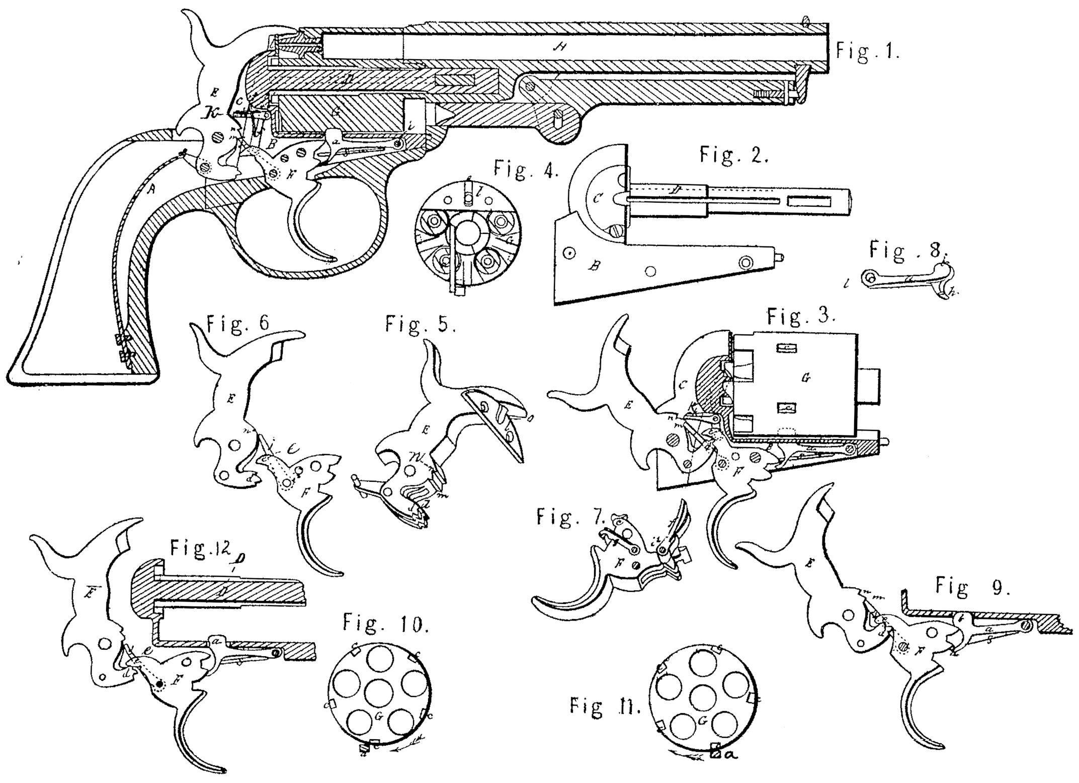
Figure 1 is a longitudinal section of a pistol constructed with my improvements. Fig. 2 is a side view of the lock-frame, recoil-shield, and arbor. Fig. 3 is a side view of the revolving breech and parts of the lock, the hammer being at full-cock, the lock-frame and recoil-shield, to which the parts are attached, being shown in section. Fig. 4 is a rear end view of the revolving cylinder, showing the relative position of the gate on the recoil-shield. Fig. 5 is a perspective view of the hammer, and of the gate detached from the recoil-shield. Fig. 6 is a representation of the extra hammer (designed to be used to make the pistol solely hammer-cocking) and the trigger. Fig. 7 is a perspective representation of the trigger with the hand and cock pawl attached. Fig. 8 represents my improved locking-bolt. Fig. 9 represents the hammer and trigger and locking-bolt in their respective positions when at full-cock. Fig. 10 is a transverse section through the charge-cylinder, showing the position of the locking-bolt and the recess in the cylinder in my improvement. Fig.11 shows the relative position of the locking-bolt and recess in the cylinder as heretofore constructed.
In the several figures like letters of reference denote similar parts of the pistol.
In order to enable others skilled in the art to construct and use my improvements in revolving-breech fire-arms, I will proceed to describe the construction and operation of the various features of my invention.
Fig. 1 represents in section a revolving breech pistol furnished with my improvements. Many parts of the pistol are well known and need not to be minutely described.
A is the handle or stock of the pistol; B, the lock-plate, to which the several parts of the lock are attached, connected with which are the recoil-shield C and arbor or base-pin D.
E is the hammer, F the trigger, G the revolving charge-cylinder or breech, and H the barrel.
My first improvement is the use, in trigger operating revolving-breech fire-arms, of a positive locking-bolt, by which term I mean a locking-bolt so constructed and arranged as to be pressed continually against the periphery of the charge-cylinder, and by entering a recess therein locking the cylinder in place, excepting just at the time that the cylinder is rotated in order to bring a fresh charge-chamber in range with the hammer and barrel, when the locking-bolt is momentarily withdrawn for that purpose.
In revolving fire-arms as ordinarily constructed there are various kinds of locking-bolts and other devices employed for locking the cylinder in place at the moment of firing, while at other times the cylinder is free to rotate if the hammer be partially raised. It is very important, however, in order to the security and efficiency of these fire-arms, especially where they are susceptible of operation by trigger, that the charge-cylinder should be locked in place at all times, excepting when it is necessary to release it in order to its revolution, and this I effect in the following manner:
In the drawings, a is the locking-bolt, the shape of which is shown ill perspective in Fig. 8. It is pivoted to the lock-frame B near to its forward end, at i, and is pressed upward by a spring, s, which is screwed to the lock-frame. The locking-bolt has a head, b, (see Fig. 8,) which passes up through an opening in the lock-frame, a little to the left of the center of the frame, for a reason hereinafter explained, and presses against the surface of the revolving breech G, entering the recesses c in the revolving breech, and thereby holding it fast and preventing its rotation excepting When the locking-bolt is withdrawn. These recesses c are equal in number to the charge-chambers. in the breech, and are so situate in relation to the locking-bolt that when a recess is engaged there with one of the charge-chambers shall be exactly in range with the barrel H and hammer E. By the locking-bolt thus constructed and arranged the charge-cylinder would be locked continually; but as it is necessary to release it in order to effect its revolution, this is done as follows:
The pistol represented in Fig. 1, constructed as there shown, is double acting— that is, may be cocked either by raising the hammer by hand or by simply pulling the trigger; but whether operated in one way or the other the action of the locking-bolt is the same, for when the hammer E is drawn back its toe presses up against the heel e of the trigger F and depresses the forward end of the trigger, drawing the trigger back in like manner as if it were pulled by hand. The hand or driver f, by which the cylinder is revolved, is pivoted to the trigger at i^@, and is raised by the drawing back of the trigger. Just at the time when the point of the hand f engages one of the notches in the end of the revolving breech-and is beginning to turn it a spring-catch, g, attached to the left side of the trigger, as seen in Fig. 7, and which has a lateral motion, catches on the upper side of a hooked projection, h, which projects downward under the head of the bolt a, as seen Fig. 8, and withdraws the bolt from its recess, as seen in Fig. 9; but as soon as the bolt-lead is clear of the recess in the cylinder the end of the spring-catch g slips over the hook of the projection h, and when the cylinder is revolved sufficiently far for the head of the bolt to enter another recess, c, in the periphery of the cylinder the bolt is free to rise up into.its place. Whenever the trigger is released and recovers itself for repeated action the spring-catch g, as it passes the hooked projection h of the locking-bolt, is pushed by it to one side, and so passes up over the hooked projection h, ready to engage it again the next time the piece is cocked. Thus it will be seen that the locking-bolt keeps the cylinder locked at all times, excepting when the cylinder is revolving from one notch to another.
Another feature of my improvement is the placing of the locking-bolt to the left hand of the axis or center of the pistol when the cylinder revolves, as is usual, from left to right; or on the right-hand side if the cylinder should be. made to revolve in an opposite direction.
The object of this is twofold: first, it insures the entrance of the head of the locking-bolt into its recess c in the cylinder, and, next, it secures the locking of the cylinder after its rotation, before the hammer is at full-cock, whether it be cocked by hand or by trigger. These effects, produced by placing the locking-bolts on the left of the center of the pistol, will be seen by reference to Figs. 10 and 11. The cylinder G revolves in the direction of the arrows. By the old method of placing the locking-bolt on the right side of the center it will be seen that the pressure of the bolt upward against the cylinder in a direction opposite to that in which it revolves tends to retard its motion and causes it to drag. The position of the bolt in relation to the recess is below it, so that when the edge of the head of the bolt passes the edge of the recess the cylinder will move more freely and will be apt to jump so as to carry the recess c past the bolt-head b; and when this happens the cylinder will not be in range and will not be locked. By my improvement, however, this accident can never happen, because as the head of the bolt b presses upward on the cylinder in the direction in which it revolves, as seen in Fig. 10, it rather helps it round than otherwise, and when the recess c reaches the head of the bolt b, the head of the bolt b being above the recess c, the bolt is sure to slip in its recess; and when the head of the bolt reaches the edge of the recess it has sufficient bearing to carry it forward faster than the hand or driver of would do, and thus the bolt enters the recess c and locks the cylinder in all cases before the hammer reaches the point of full-cock.
In other revolving fire-arms it is usual to make the locking-bolt to operate to lock the revolving cylinder at the moment of firing by means of the trigger pressing it upward. In my fire-arm, however, the locking-bolt has positive locking action of its own independently of the trigger, and by this means I gain an additional security that the cylinder shall be rigidly held in place not otherwise attainable, for as the hand f, by which the cylinder is revolved, is operated by drawing back the trigger the cylinder is thereby pressed firmly against the head of the locking-bolt in the recess, which, acting independently of the trigger, serves to double-lock the cylinder in place.
My improvement further consists in the use of a gate either attached to or forming part of the recoil-shield, which will permit of the end of the hammer passing through it to strike the cap on the end of the nipple, while it is too narrow to allow the spent caps from passing backward into the recess in the recoil-shield, in which the hammer rests when not raised. This gate is shown in Figs. 4 and 5, and consists of a steel or iron plate, l, of the shape of the segment of a circle, attached to or forming part of the recoil-shield, which partially covers the mouth of the recess for the hammer in the recoil-shield, but has a narrow notch, o, through which the point p of the hammer may pass far enough to strike the cap on the nipple in front of it. The notch o is, however, too small to allow of the spent caps passing through it, and thus obviates the serious annoyance of the prevention of the fall of the hammer, and the consequent missing of fire, if a cap should be lodged in the hammer-groove of the recoil-shield. The use of this gate also serves to keep the spent caps in place, and thus enables the cylinder to move round more freely.
Another improvement, designed to prevent the fouling of the base-pin or arbor D and breech. G and to aid in lubricating the base-pin, consists in making one or more longitudinal grooves, q, along so much of the base-pin as is covered by the revolving breech, the groove or grooves q being parallel with the axis of the cylinder and base-pin. The effect of this construction is to clean off the dirt which accumulates on the arbor or base-pin of revolving fire-arms and deposit it in the grooves or groove, which also serve as a depository for the oil to lubricate the base-pin. I am aware that a spiral groove has been used for this purpose; but it does not answer the purpose nearly so well, and it has the effect of running the oil out from the spindle instead of retaining it in the bore of the cylinder.
Having thus described my improvement in revolving-breech fire-arms, what I claim as my invention, and desire to secure by Letters Patent, is—
1. The use, in revolving fire-arms susceptible of being operated by the trigger, of a positive locking-bolt for locking the revolving breech independently of the action of the trigger at all times, excepting when the cylinder is being revolved, substantially as hereinbefore described.
2. Placing the locking-bolt on the left-hand side of the axis of the revolving cylinder where the cylinder revolves from right to left, and vice versa, where it moves in the opposite direction, for the double purpose of insuring the entry of the lead of the bolt into its recess or notch in the cylinder and of aiding the revolution of the cylinder just before firing, so as to lock the breech before the hammer is at full-cock, substantially as described.
3. Double-locking the cylinder at the moment of firing, so as to hold it perfectly rigid, by means of the hand or driver operated by the trigger to sustain it in one direction, and the locking-bolt to receive the pressure and sustain it in the opposite direction, substantially as described.
4. The use of a gate attached to the recoil-shield placed at the end or throat of the hammer-recess, having a narrow slot or hole of less width than a percussion-cap, to allow of the passage of the point of the hammer to strike | the cap for the purpose of preventing the passage of spent caps into the hammer-recess, and also to prevent the caps from projecting so far backward as to interfere with the rotation of the revolving breech, substantially as described.
5. The use of a groove or grooves in the arbor or base-pin of revolving-breech fire-arms where such groove or grooves are parallel to the axis of the base-pin, for the purposes here in before described.
6. So constructing and arranging the hammer, trigger, and driver of hammer-cocking revolving-breech fire arms as that the cocking of the hammer will draw back or set the trigger, holding it in a drawn position so as to be fired by a mere touch, substantially as described, and for the purposes set forth.
In testimony whereof the said J. Maslin Cooper hath hereunto set his hand in presence of us.
J. MASLIN COOPER.
Witnesses:
W. Bakewell,
J. D. Hancock.