
US 210506
UNITED STATES PATENT OFFICE.
WILLIAM W. DODGE, OF WASHINGTON, DISTRICT OF COLUMBIA.
IMPROVEMENT IN LOCKS FOR FIRE-ARMS.
Specification forming part of Letters Patent No. 210,506, dated December 3, 1878; application filed October 30, 1878.
To all whom it may concern:
Be it known that I, WILLIAM W. DODGE, of Washington, District of Columbia, have invented certain Improvements in Double-Action Locks for Fire-Arms, of which the following is a specification:
My invention relates to that class of locks for fire-arms commonly known as “double-action” locks, which are so constructed that the hammer may be raised by the thumb to the half-cock and full-cock positions, and there sustained by the trigger or sear, or both raised and released by simply pulling the trigger; and it consists in forming the hammer and trigger each with a rigid arm having a hooked end, which hooked ends are arranged to engage with each other when the hammer is raised by the thumb to the half-cock position, and to thus sustain the hammer in said position.
It further consists in providing one of said hooked arms with a notch, in which the point of the other hooked arm engages when the hammer is raised by the thumb to the full cock position, and in so arranging said arms that when the hammer is raised by the thumb it shall cause the trigger to be raised out of the line of descent of the hammer, by which construction and arrangement the rigid arms are adapted to sustain the hammer in its different positions without the aid of intermediate devices.
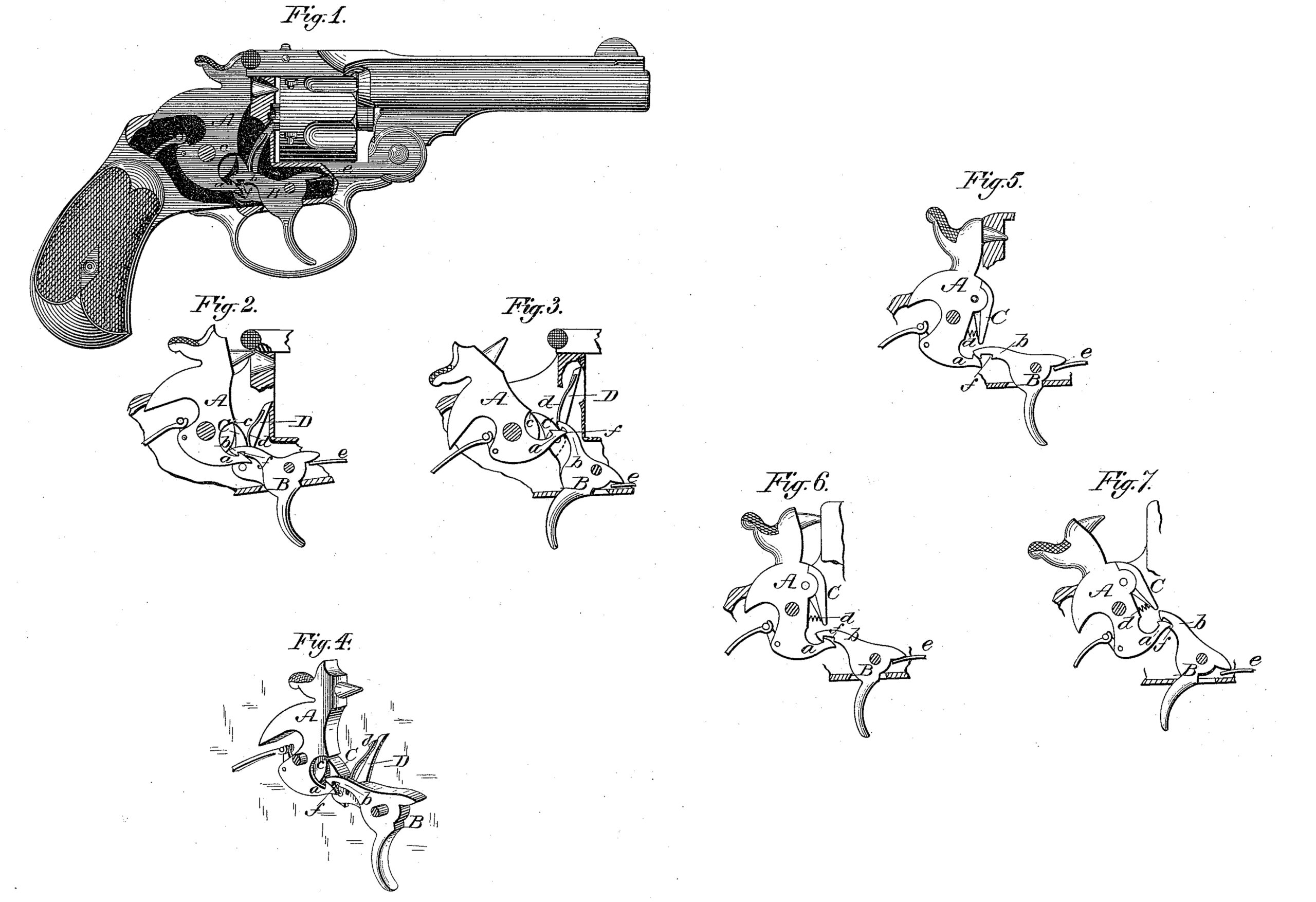
In the accompanying drawings, Figure 1 represents a side elevation of a revolver of the Smith & Wesson style having my improved lock applied, the frame being broken away to show the parts, and the hammer being shown in its normal position. Figs. 2 and 3 represent, respectively, the working parts of the lock in the half-cock and full-cock positions. Fig. 4 is a perspective view of the same in the position indicated in Fig. 1. Figs. 5, 6, and 7, respectively, represent a slightly-different form of the lock in its normal, half-cock, and full-cock positions.
Locks of this class have long been made in a variety of forms; but as commonly constructed they are more or less complicated and expensive, requiring in most cases the employment of intermediate devices between the hammer and trigger for sustaining the hammer in its different elevated positions. These parts, besides adding to the cost of construction, also render the lock more liable to get out of repair.
To obviate these difficulties and produce a strong and simple lock, cheap in construction and efficient of action, are the objects of my invention.
Locks of this style are of two general classes, one class having a pawl or arm pivoted to the trigger, and the other having the pawl pivoted upon the hammer.
As will be seen by referring to the drawings, my improvements are applicable to both forms, Figs. 1 to 4 representing them applied to one form, and the remaining figures showing them adapted to the other form.
Referring to the form shown in Figs. 1 to 4, A represents the hammer formed with a projecting hooked arm, a, at its lower end, and with a notch or shoulder, c, on its front face; and B represents the trigger, formed with a similar hooked arm, b, extending in rear of its pivot, and resting, when the hammer is down, upon the hook or end of arm a, as shown in Figs. 1 and 4. The trigger B is also furnished with a pivoted pawl, C, arranged to engage in the notch c and to cause the elevation of the hammer when the trigger is pulled, in the manner common to locks of this class.
The pawl C is held against the face of the hammer by means of a spring, d, which may be secured and arranged in any suitable manner, though in practice I prefer to arrange the parts as represented in Figs. 1, 2, 3, and 4, in which the spring d is represented as secured at one end to the cylinder-operating pawl D, and arranged to bear at its other end against the pawl C, the pivot of the pawl D also serving as the pivot of the pawl C. In this way I am enabled to avoid the use of a second spring and pivot, and thereby to lessen the cost of manufacture.
The operation of hammer by the trigger being effected in the same manner in this as in locks now in common use, I shall simply describe the manner in which the hammer is sustained in its different positions when raised by the thumb, and of raising the trigger out of the way of the hammer.
By reference to Figs. 1 and 4 it will be seen that the hook of the arm b of the trigger rests, when the hammer is down, upon the hook of the arm a of the hammer; but as the hammer is drawn back by the thumb, the arm a, riding forward, causes the shoulder of its hook to pass that of the hook of arm b, when the sear or trigger spring e, throwing down the rear end of the trigger, causes the hooks to engage with each other, as shown in Fig.2, holding the hammer in its half-cock position. By continuing the backward movement of the hammer the arm a is caused to swing upward and, bearing against the under side of the arm b, raise the latter, and with it the trigger B and its pawl C, until the point of the arm a passes the shoulder of a notch, f, formed in the arm b, when the sear-spring e again causes the rear end of the trigger to fall slightly, bringing said shoulder in front of or under the point of arm a, and thus sustaining the hammer in its full-cock position, as shown in Fig. 3, from which it may be released by pulling the trigger in the usual manner. It is, of course, necessary that the pawl C shall move out from the notch or shoulder c at the same instant that the arm b releases the arm a, in order that the hammer may descend without obstruction, and to insure this result the pawl C is formed with a stop, as shown in the several figures, by which its back ward movement is limited.
This form of lock is adapted to all that class in which the pawl is pivoted to the trigger, and is found, in practice, to work easily and with certainty.
Referring now to Figs. 5, 6, and 7, it will be seen that when applied to locks having the spring-pawl C pivoted to the hammer, the principle of operation remains precisely the same, so far as my improvements are concerned, as in the form above described, and hence it is not deemed necessary to again describe the operation.
The improvements above described may be used in connection with rebounding locks, if desired, and upon any style of arm.
By the above construction I am enabled to produce a lock simple and cheap in construction, efficient in operation, and not liable to get broken or out of order.
It is obvious that the arms a and b may be so arranged that their hooks shall engage to sustain the hammer at full instead of half cock, other devices being employed to sustain it at half-cock, and also that when arranged to sustain the hammer at half-cock, other devices than those shown and described may be employed to hold the hammer in its full-cock position.
Having thus described my invention, what I claim is–
1. The combination of a hammer and a trigger, each provided with an arm having a hooked end, so constructed and arranged that the hooks may engage with each other and sustain the hammer in an elevated, or partially elevated, position.
2. The combination of the hammer A, having a hooked and pointed arm, a, and the trigger B, having a hooked and notched arm, b, whereby the trigger is adapted to sustain the hammer in its different positions.
3. The combination of the hammer A and trigger B, each provided with a rigid hooked arm and a pawl, C, located between the hammer and trigger and pivoted to one or the other, substantially as shown, whereby the hammer is adapted to be operated by the trigger or to be sustained in an elevated, or a partially elevated, position by the engagement of the hooks, as described.
4. The combination of the hammer A, provided with the hooked arm a, the trigger B, provided with the hooked and notched arm b, and a pawl, C, located between the hammer and trigger and pivoted to one or the other, substantially as shown, whereby the hammer is rendered capable of elevation and release by means of the hammer and trigger jointly or by the trigger alone, substantially as described.
WILLIAM W. DODGE.
Witnesses:
P. T. DODGE,
DONN I. TWITCHELL,