
US 391153
UNITED STATES PATENT OFFICE
IVER JOHNSON AND ANDREW FYRBERG, OF WORCESTER, MASSACHUSETTS;
SAID FYRBERG ASSIGNOR TO SAID JOHNSON.
REVOLVING FIRE-ARM.
SPECIFICATION forming part of Letters Patent No. 391,153, dated October 16, 1888.
Application filed March 27, 1888. Serial No. 268,675 (No model.)
To all whom it may concern:
Be it known that we, IVER JOHNSON and ANDREW FYRBERG, both of Worcester, in the county of Worcester and State of Massachusetts, have invented certain new and useful Improvements in Revolvers; and we do hereby declare that the following is a full, clear, and exact description thereof, reference being had to the accompanying drawings, forming a part of this specification, and in which-
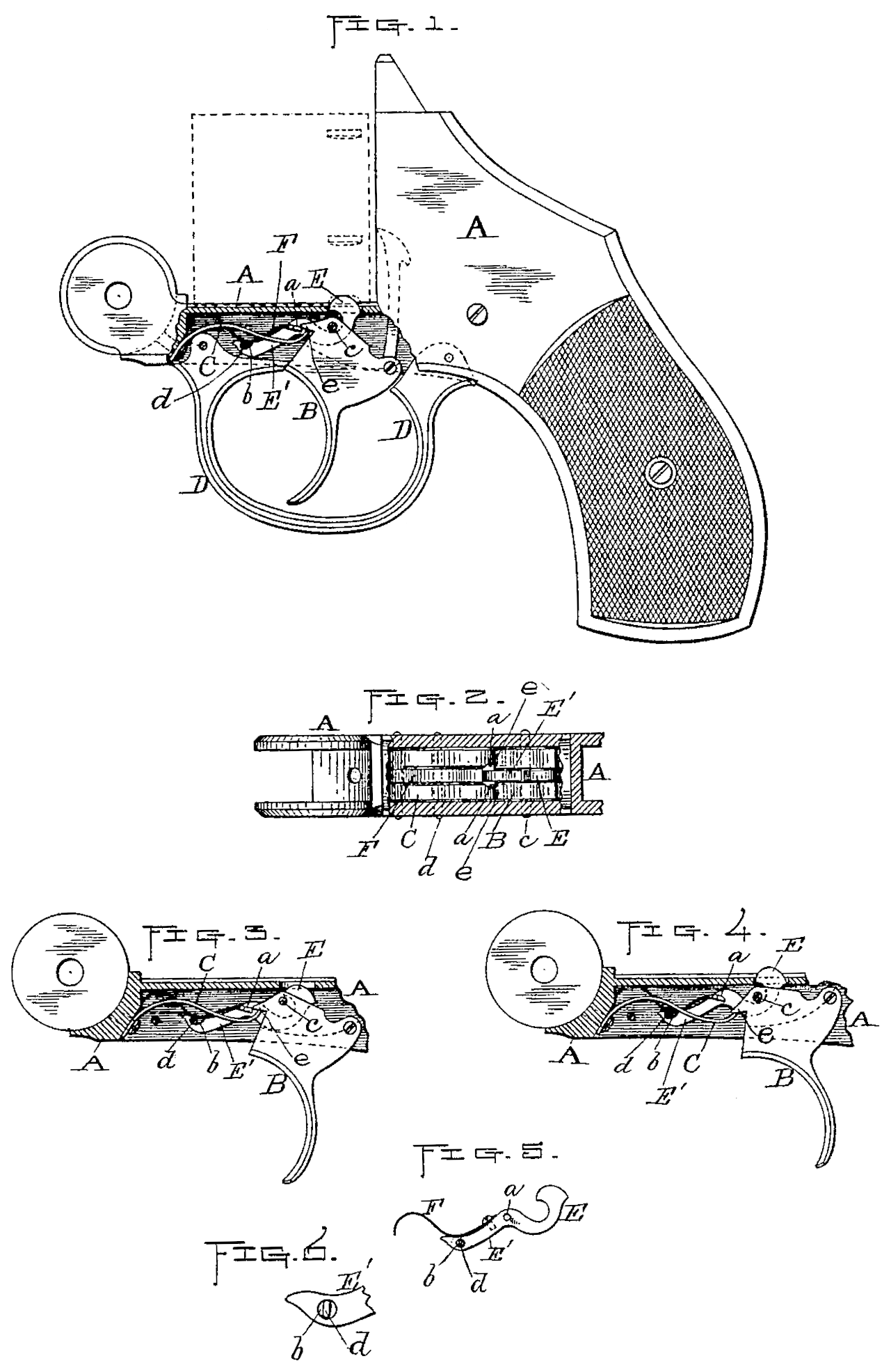
Figure 1 represents a side view of so much of a revolver as is necessary to illustrate our improvements thereon, portions thereof being broken away to better show said improvements. Fig. 2 is a horizontal section of a part of the revolver, showing also a plan view of our improvements. Figs. 3 and 4 are views similar to Fig. 1 of parts relating to said improvements, showing the operation thereof, as hereinafter described. Fig 5. Shows modifications in the construction of the cylinder stop–lever, also hereinafter described; and Fig. 6 is an enlarged view of the forward end of said cylinder stop-lever shown in Fig. 5.
Our invention relates to the cylinder stop mechanism of a revolver; and it consists in the construction and relative arrangement of the various parts composing the said mechanism, as set forth in the following specification.
Referring to the drawings, the parts marked A represent the frame; B, the trigger; C, the trigger-spring; D, the trigger guard, and E the cylinder stop lever of the revolver.
The principal feature of our invention consists in making said cylinder stop-lever E with a forward extension, E’, of irregular shape, and provided with a spring, F, also having the lateral cam projections a a upon opposite sides thereof, and a transverse guide-slot or opening, b, near its forward end. Said stop-lever E is arranged under the trigger-pivot c in a vertical longitudinal slot in the upper end of the trigger and a vertical slot in the trigger-spring C, (see Fig. 2) and its forward end engages with a transverse pin, d, fastened in the frame, said pin passing through the slot or opening b before alluded to. Said slot and pin are made so as to admit of a slight longitudinal movement of the lever, as and for the purpose hereinafter described.
In Figs. 1, 3, and 4 we have shown the slot open at the top, a little longer than the diameter of the pin, and of the proper shape at the forward end to nearly encircle the pin, so that the lever will hold against said pin, being thus held by the constant forward and upward pressure of the spring F, which has a bearing at its forward circular end against the revolver-frame and near its center against the top of the pin. The lever, being thus hinged to the pin, and the rear end of the spring connected with said lever at a considerable distance back of said pin, causes, as will be seen, a back draft of the lever against the pin, and at the same time an upward pressure to hold the same in its normal elevated position, as shown in Figs. 1 and 4. Said upward movement is controlled by the lever coming against the under side of the trigger pivot-pin, as is also shown in said figures. The rear end of the lever is depressed to withdraw said end from the cylinder-notch, so that said cylinder may be turned by the fingers e e on the front side of the trigger engaging with and bearing down upon the lateral projections a a on said lever, when the trigger is pulled back in the usual way. (See Fig. 3) Said fingers and projections are in practice so constructed and arranged in relation to each other that when the trigger is pulled back, as aforesaid, the fingers will first press down upon the tops of the projections, and then as the downward movement is continued against the curved or cam surfaces at the rear sides of the projections, thus causing the lever to be sprung not only down, but also forward end-wise, so that the fingers may pass down by its projections and allow the stop to be snapped by its spring F into the next notch in the cylinder as the latter is turned and said notch brought in line therewith. In order that the lever may be thus sprung forward by the pressure of the fingers e on the projections a, the lever-spring is so made as to yield to such pressure. In this instance said result is accomplished by making the forward end of said spring in about the form of a half circle or bow, curving upward from its bearing-point over pin d, and then down at its forward extremity, so that its flat surface at said end may bear against the frame A, as shown in Figs. 1, 3, and 4. We do not limit ourselves, however, to this construction. Neither do we limit ourselves to making the transverse slot b in the front end of the lever in the manner previously described, as a like result may be effected by making a circular or other shaped opening transversely through said lever, closed at the top, as shown in Figs 5 and 6, in which case it is preferable to flatten the sides of the pin d where it passes through, as best shown in Fig. 6.
The yielding action of the lever, it will be understood, also admits of the trigger-spring forcing the fingers up past the projections into their normal positions, when the pressure on the trigger is released.
In the first four figures of the drawings we have shown the cam projections a a in a continuous line with the back end of the lever-spring, and in practice they are preferably formed upon said spring and fastened to the lever by inserting said enlarged end in a transverse slot formed in said lever; but, if desired, instead of said construction, the spring may be fastened independent of the projections, and said projections produced by forming the same on the side of the lever, or by fastening a pin transversely therein, as is shown in Fig. 5.
In Fig. 1 we have shown the parts to which our improvements relate in their normal positions. In Fig. 3 the trigger is shown pulled back part way, with the fingers e e just passing over the cam-surfaces of the projections a a after depressing the lever, and just preparatory to releasing the same, so that it may be sprung up, as previously described; and in Fig 4. The trigger is shown pulled clear back and the lever released preparatory to releasing and allowing said trigger to be sprung back into its normal position.
We are aware of the United States Patents to G. W. Cilley, No. 254,798, dated March 14, 1882, and to J. T. Smith, No. 336,021, dated February 9, 1886, for improvements in revolvers, both of which show spring devices for cylinder stops or locks, and make no claim to the constructions therein set forth.
What we do claim, and desire to secure by Letters Patent, is-
In a revolver or similar fire-arm, a cylinder-stop or lock-lever adapted to engage with the cylinder-notched at its upper rear end, arranged under the trigger-pivot in suitable vertical slots in said trigger and the trigger-spring, and hinged at its forward end on a stationary transverse pin, also having a suitable spring for exerting a yielding backward and upward pressure thereon, and lateral cam projections upon the sides thereof, in combination with the trigger having suitable fingers or projections adapted to engage with the cam projections aforesaid, its pivot, and spring, substantially as shown and specified.
IVER JOHNSON
ANDREW FYRBERG
Witnesses:
A. A. Barker,
W. B. Nourse.